22 SUPERSTAR II User Manual Rev 3
Chapter 3 Installation
3.3.3 Data Link
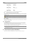
The data link for differential operation must operate at a minimal rate of 9600 bps.
3.3.4 Base Station and Rover Units Separation
The operational range of carrier-phase differential measurements is limited to about 20 km, after which
significant accuracy degradation can occur. If your application requires greater separations, your own base
station network must be established.
3.4 Connectors and Connector Pins Assignment
The receiver has two standard connectors.
• J1 is a 20-pin connector for general input/output interfaces and power input
• J2 is a MCX type RF connector.
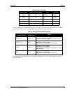
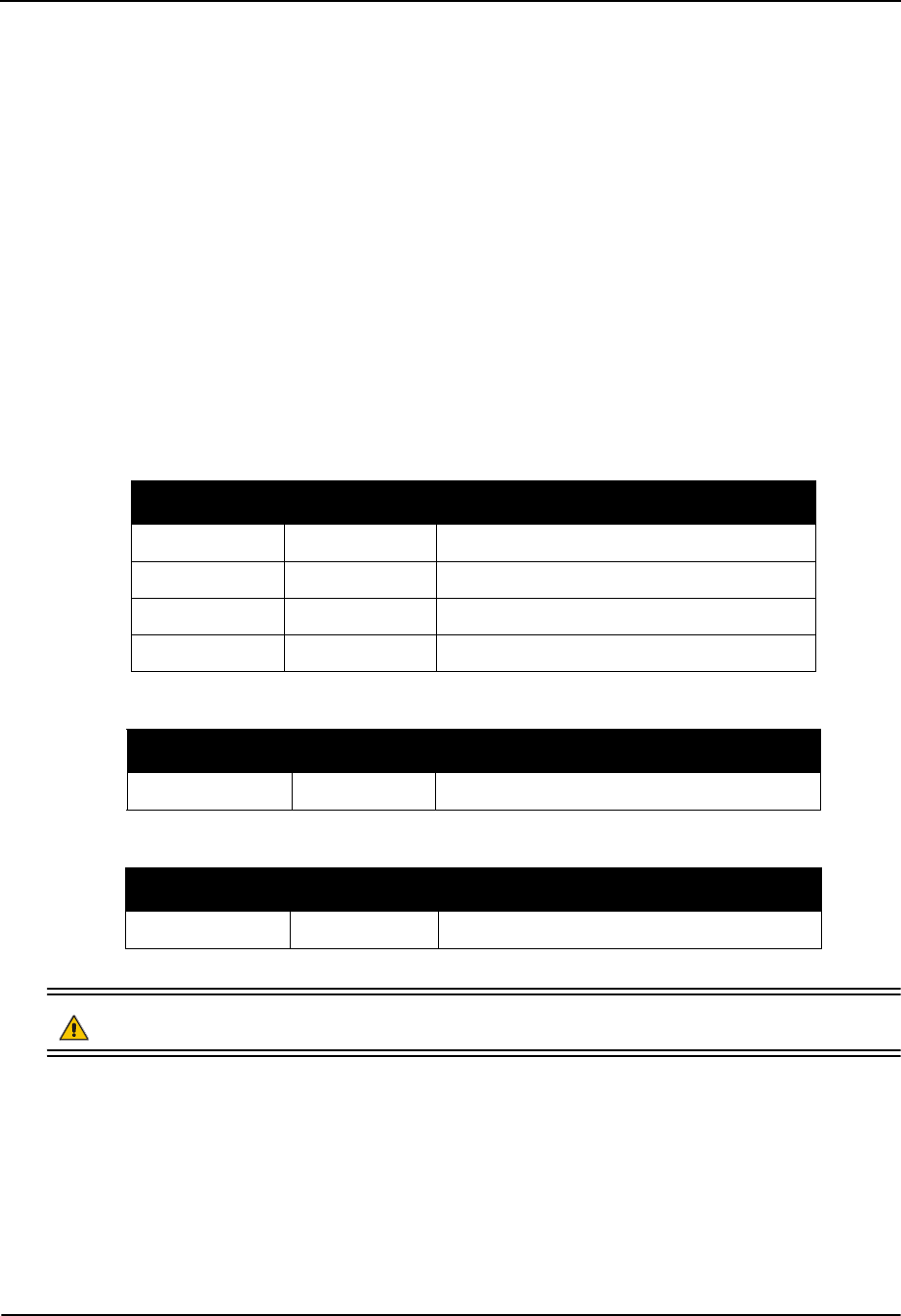
The minimum number of connections on J1 required for the system to operate is shown in Table 2.
Table 2: Minimum J1 Connections
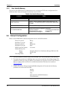
If DGPS corrections are required for the application, the SUPERSTAR II can receive them on COM2:
If an active antenna is used:
CAUTION: You should use a current-limiting power source. The maximum current is 40 mA.
See Appendix A, Technical Specifications, starting on Page 44 for more details.
3.4.1 J1 Interface and Power Connector
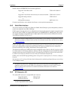
The SUPERSTAR II connector is a 2mm straight 2x10 pin header:
Suggested supplier: Samtec
On-Board connector: TMM-110-03-T-D.
Signal Name J1 Pin # Description
VCC 2 Primary power (3.3V or 5.0V -0.5 V/+0.25 V)
GND 10, 13, 16 & 18 Ground
TX_No_1 11 Serial port Tx #1
RX_No_1 12 Serial port Rx #1
Signal Name J1 Pin # Description
RX_No_2 15 Serial port Rx #2
Signal Name J1 Pin # Description
PREAMP 1 Power for active antenna (40 mA max)


