42 SUPERSTAR II User Manual Rev 3
Chapter 7 Troubleshooting
When your receiver appears not to be working properly, often there are simple ways to diagnose and resolve
the problem. In many cases, the issue can be resolved within a few minutes, avoiding the hassle and loss of
productivity that results from having to return your receiver for repair. This chapter is designed to assist you in
troubleshooting problems that occur and includes resolutions to aid your receiver in becoming operational.
If you are unsure of the symptoms or if the symptoms do not match any of those listed, use Message ID# 51,
Initiated BIT and refer to its description in the L1 GPS Firmware Reference Manual.
If the problem is not resolved after using this troubleshooting guide, contact Customer Service, see Page 9.
This section is intended to assist you in the use of our SUPERSTAR II product.
1. If you are having problems communicating with the SUPERSTAR II product:
• Verify connection: look for broken pins, a misaligned connector or intermittent contact.
• Verify power supply input is acceptable e.g. at a good level, low ripple, and not noisy.
• Verify the Receive/Transmit ports are going to the correct ports on the host computer. Check
signal directions and voltage levels.
• Verify communication settings match the host computer for both protocol and baud rate.
2. If you are experiencing problems with low SNR levels:
• Verify antenna connector, look for broken or poor connections on the RF signal/shield
contacts.
• If using an active antenna, verify antenna is receiving correct power from RF connector;
preamp input into SUPERSTAR II is feeding a DC bias on the center conductor.
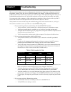
• Verify cable length from the antenna to SUPERSTAR II; signal will be attenuated based on
this length. For best performances, ensure the gain at the input of the receiver is between -3
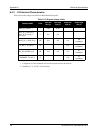
dB and 8 dB, see Table 6 below (for RG-58/U LLDS80 cables):
Table 6: Cable Lengths Vs. Gain
• Check antenna's installation, verify there is a clear view of the sky (i.e. no obstructions) and
there is no reflective surface nearby that may cause multipath interferences.
• Verify the effectiveness of your EMI / EMC shielding. Close proximity to high energy
sources (both digital & RF circuitry) can affect your SUPERSTAR II’s performance.
• Verify the cleanness (i.e. low ripple, minimum noise spikes, voltage level variations) of the
power source. Isolate the power supply of the SUPERSTAR II from the main system power.
• Check digital, RF and power ground returns. Look for noise being coupled on ground return
paths.
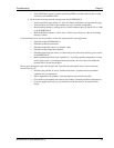
3. If you are not receiving differential corrections:
• Check DGPS connection on COM2 (port #2) of the SUPERSTAR II.
• Verify DGPS source settings are active.
Antenna Gain
Min Cable Length
(Loss)
Max Cable Length
(Loss)
Signal Level
at Input
0 dB 0m (0 dB) 3m (3 dB) 0 dB / -3 dB
+12 dB 5m (4 dB) 25m (15 dB) 8 dB / -3 dB
+26 dB 30m (18 dB) 54m (31 dB) 8 dB / -3 dB
+36 dB 49m (28 dB) 69m (39 dB) 8 dB / -3 dB


