67
CIO Area Allocations Section 4-3
4-3 CIO Area Allocations
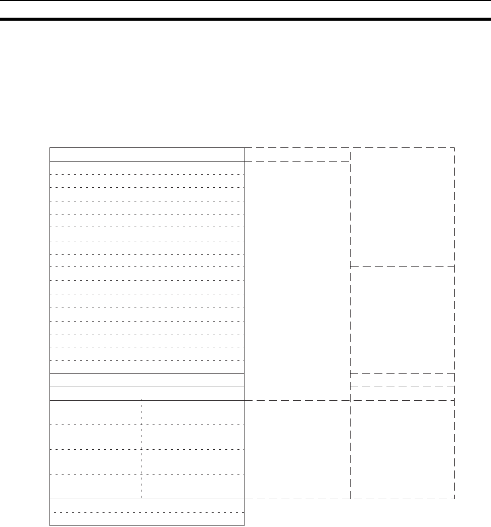
The various kinds of data are stored in the offset positions shown in the fol-
lowing diagram, from the beginning word in the area for each Unit.
The beginning word n is calculated by the following equation:
Beginning word n = CIO 1500 + (25 x unit number)
The following items in the diagram can also be checked using software switch
settings on the CX-Programmer.
• The status of UDP/TCP sockets 1 to 8 (Opening Flag, Receiving Flag,
Sending Flag, Closing Flag, Results Storage Error Flag, Socket Open
Flag)
• Service status (FTP status)
For explanations of how to use the related communications services listed in
the above diagram, refer to the indicated sections.
Offset
Bit
Data direction
Related communications services
Unit Control Switch
UDP Socket No. 1 Status
TCP Socket No. 1 Status
Service Status
Error Status
Socket Service Re-
quest Switches 5
Socket Service Re-
quest Switches 6
(Not used.)
(Not used.)
CPU Unit to Ethernet Unit
Ethernet Unit to CPU Unit
CPU Unit to Ethernet Unit
Socket Services
Mail Function
Socket Services
Socket Services
FTP Service, etc.
All error conditions
TCP Socket No. 2 Status
TCP Socket No. 3 Status
TCP Socket No. 4 Status
TCP Socket No. 5 Status
TCP Socket No. 6 Status
TCP Socket No. 7 Status
TCP Socket No. 8 Status
UDP Socket No. 2 Status
UDP Socket No. 3 Status
UDP Socket No. 4 Status
UDP Socket No. 5 Status
UDP Socket No. 6 Status
UDP Socket No. 7 Status
UDP Socket No. 8 Status
Socket Service Re-
quest Switches 7
Socket Service Re-
quest Switches 8
Socket Service Re-
quest Switches 1
Socket Service Re-
quest Switches 2
Socket Service Re-
quest Switches 3
Socket Service Re-
quest Switches 4
n
n+1
n+2
n+3
n+4
n+5
n+6
n+7
n+8
nn+9
n+10
n+11
n+12
n+13
n+14
n+15
n+16
n+17
n+18
n+19
n+20
n+21
n+22
n+23
n+24+
15 8 7
0
(Refer to Section 6
Socket Services.)
(Refer to Section 6
Socket Services.)
(Refer to Section 8 Mail.)
(Refer to Section 6
Socket Services.)


