189
Internode Test Section 9-3
Starting and Stopping the Internode Test
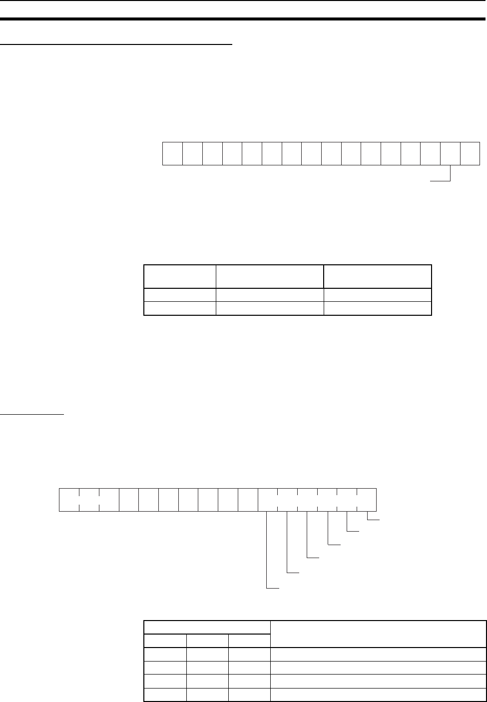
Bit 01 of the first word in the words allocated to the Ethernet Unit in the CPU
Bus Unit Area is used as the Internode Test Start Switch. Turn ON bit 01 to
start the internode test and turn bit 01 OFF to stop the internode test. The
address of the word containing the Internode Test Start Switch is calculated
by the following formula:
Word = 1500 + (25 x unit number)
The internode test run status can be confirmed using the TS indicator on the
Unit’s front panel or the Internode Test Flag (error status, bit 8) in the allocated
words in the CIO Area.
Error status area (1 word) = CIO 1500 + (25
× unit number) + 18
9-3-2 Checking Results
The results of the internode test are stored in the fourth through ninth words of
the portion of the CPU Bus Unit Area allocated to the Ethernet Unit. The sta-
tus information area stores the test status and numbers of test runs and
errors.
Test Status
The result of the test run and descriptions of errors are stored as the test sta-
tus. The test status is stored at the word whose address is calculated by the
following formula:
Word = D03000 + (100 x unit number) + 3
Error Code If the test is run repeatedly, the code for the latest test results is stored.
TS indicator Internode Test Flag
(error status, bit 8)
Run status
Lit 1 Internode test running
Not lit 0 Internode test stopped
−
15
−
14
−
13
−
12
−
11
−
10
−
9
−
8
−
7
−
6
−
5
−
4321
−
0
Bit
Internode Test Start Switch
0: Stop internode test
1: Start internode test
15 14 13
0
12
0
11
0
10
0
9
0
8
0
7
0
6543210
Error code Error flags
1: Send parameter error
1: Routing table error
1: Data not matched
1: Send error
1: Response error
1: Timeout error
+3
Bit
Bit Description
15 14 13
000Normal
0 0 1 Timeout error
0 1 0 Response (response code) error
0 1 1 Send error


