


39
Connecting to the Network Section 3-6
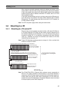
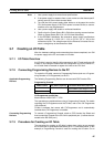
3-6 Connecting to the Network
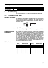
3-6-1 Ethernet Network Installation
When installing an Ethernet network, be sure to take all appropriate safety
measures and to follow the applicable standards (ISO 8802-3). You must
obtain a copy of these specifications and be sure you understand them before
attempting to install an Ethernet System. Unless you are already experienced
in installing communications systems, we strongly recommend that you
employ a professional to install your system.
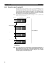
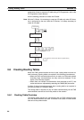
For information regarding basic installation precautions, equipment, recom-
mended products, and installation examples, refer to Appendix A Network
Installation.
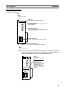
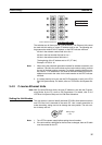
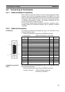
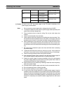
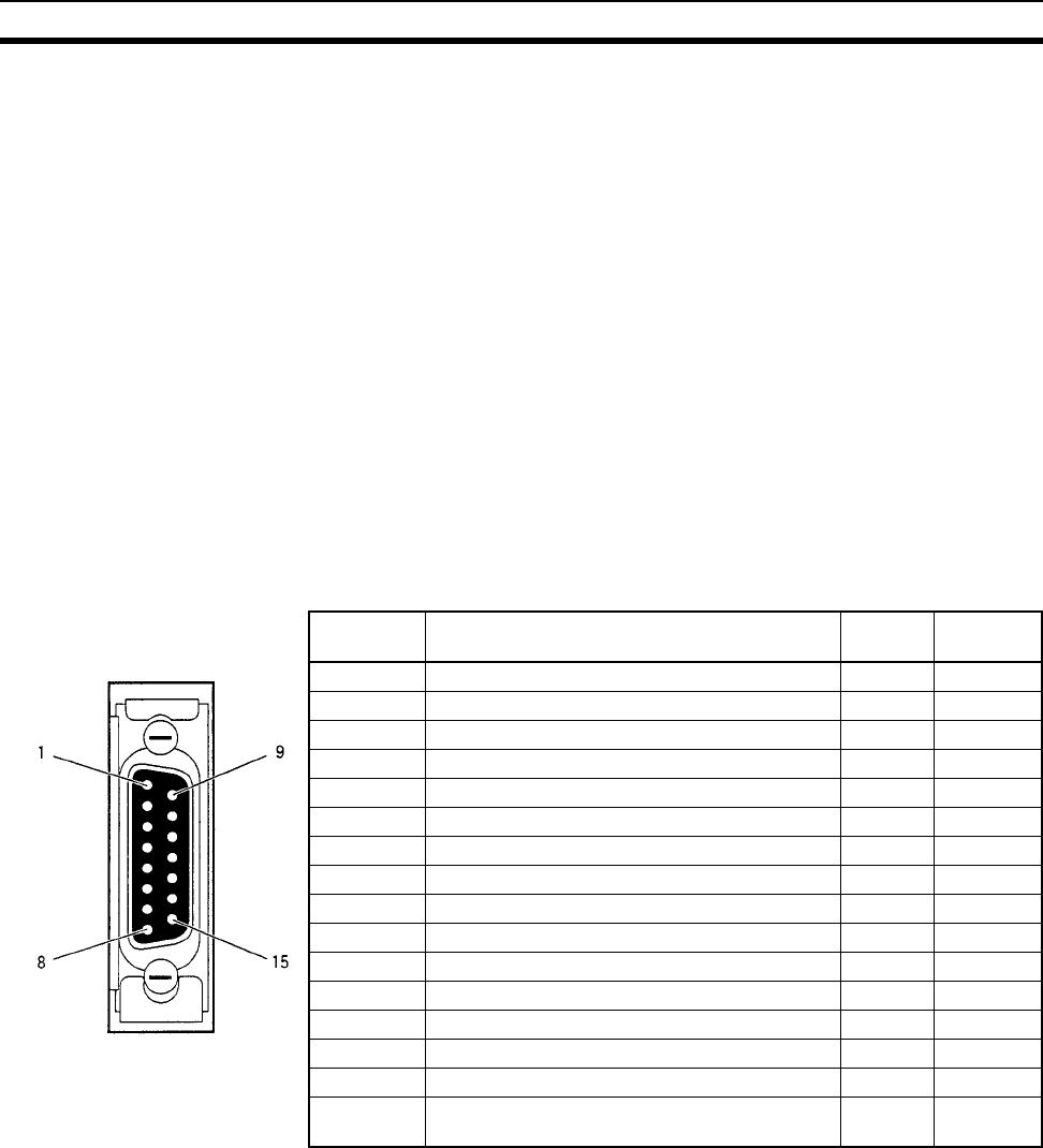
3-6-2 Ethernet Connectors
CS1W-ETN01 The following standards and specifications apply to the connectors for the
Ethernet transceiver cable.
• Electrical specifications: Conforming to IEEE802.3 standards.
• Lock structure: IEEE802.3 standards for slide latches
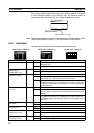
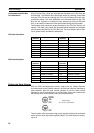
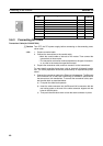
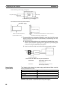
CS1W-ETN11 and CJ1W-
ETN11
The following standards and specifications apply to the connectors for the
Ethernet twisted-pair cable.
• Electrical specifications: Conforming to IEEE802.3 standards.
• Connector structure: RJ45 8-pin Modular Connector
(conforming to ISO 8877)
Connector
pin
Signal name Abbr. Signal
direction
1 Signal ground GND ---
2 Collision detection signal + COL+ Input
3 Send data + TX+ Output
4 Signal ground GND ---
5 Receive data + RX+ Input
6 Power ground (common with signal ground) VC ---
7 Not used --- ---
8 Signal ground GND ---
9 Collision detection signal – COL– Input
10 Send data – TX– Output
11 Signal ground GND ---
12 Receive data – RX– Input
13 Transceiver +12 VDC power supply +12 V Output
14 Signal ground GND ---
15 Not used --- ---
Connector
hood
Frame ground FG ---