


12
2. Hole and
Land
diameter
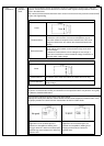
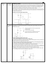
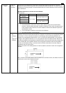
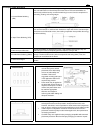
The Hole and Land diameter are made with the hole slightly larger than the lead wire so that the
component may be inserted easily. Also, when soldering, the solder will build up in an eyelet condition,
increasing the mounting strength. The standard dimensions for the Hole diameter and Land are shown
in the table below.
Standard dimensions for the Hole and Land diameter
Unit: mm/ inch
Standard Hole
di t
Tolerance Land diameter
0.8/ .031
1.0/ .039
2.0 to 3.0/ .079 to .118
1.2/ .047
1.6/ .063
±0.1/ ±.039
3.5 to 4.5/ .138 to .177
Remarks
• The Hole diameter is made 0.2 to 0.5mm/ .008 to .020inch larger than the lead diameter.
However, if the jet method (wave type, jet type) of soldering is used, solder may pass through
to the component side. Therefore, it is more suitable to make the Hole diameter equal to the
lead diameter +0.2mm.
• The Land diameter should be 2 to 3 times the Hole diameter.
• Do not put more than 1 lead in one hole.
14. PC board
design
3. Expansion
and
shrinkage
of
copper-clad
laminates
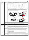
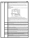
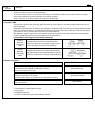
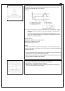
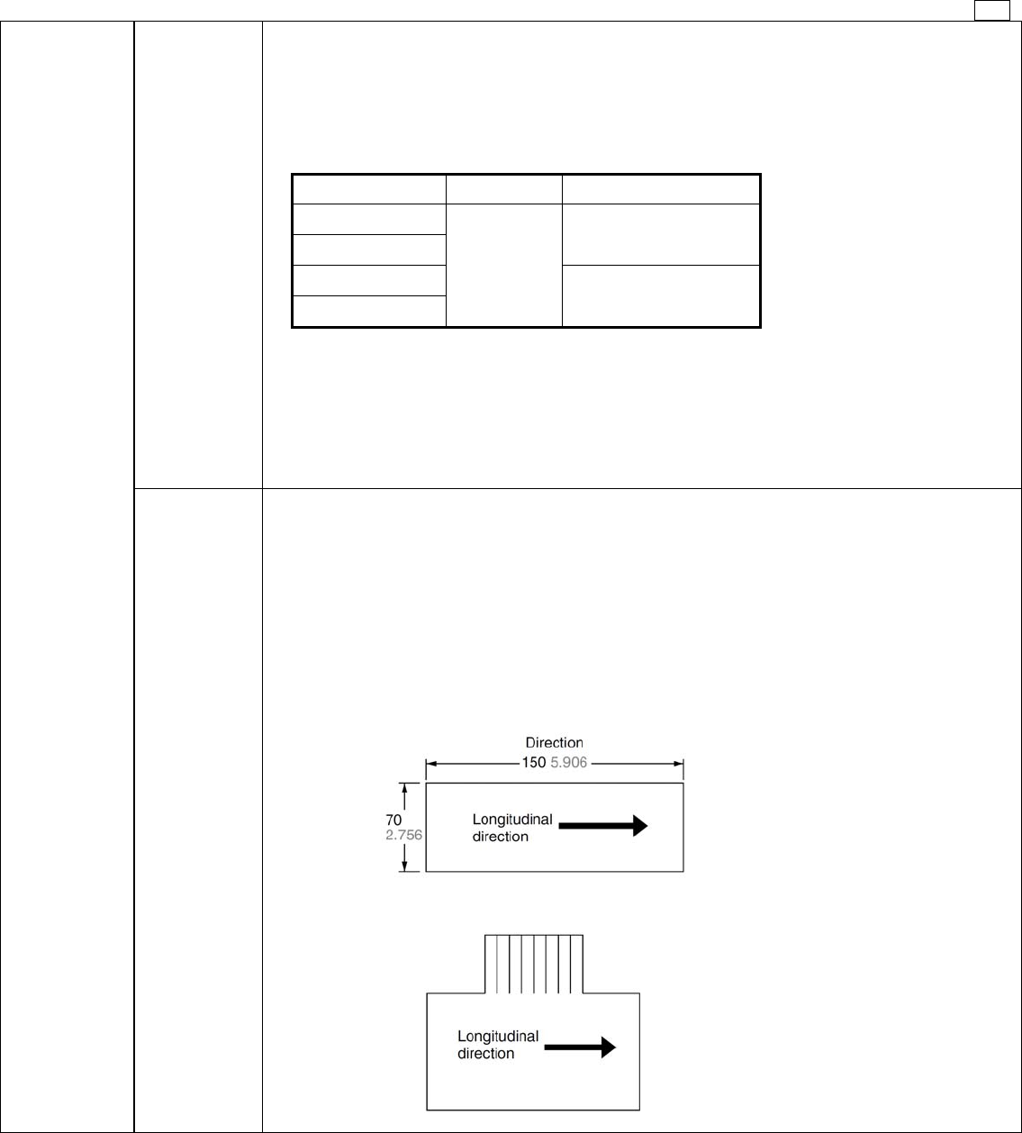
Because copper-clad laminates have a longitudinal and lateral direction, the manner of punching
fabrication and layout must be observed with care. Expansion and shrinkage in the longitudinal direction
due to heat is 1/15 to 1/2 of that in the lateral, and accordingly, after the punching fabrication, the
distortion in the longitudinal direction will be 1/15 to 1/2 of that in the lateral direction. The mechanical
strength in the longitudinal direction is 10 to 15% greater than that in the lateral direction. Because of
this difference between the longitudinal and lateral directions, when products having long configurations
are to be fabricated, the lengthwise direction of the configuration should be made in the longitudinal
direction, and PC boards having a connector section should be made with the connector along the
longitudinal side.(The figure below)
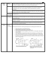
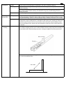
Example: As shown in the drawing below, the 150mm (5.906 inch) direction is taken in the longitudinal
direction.
Also, as shown in the drawing below, when the pattern has a connector section, the direction is taken as
shown by the arrow in the longitudinal direction.