7
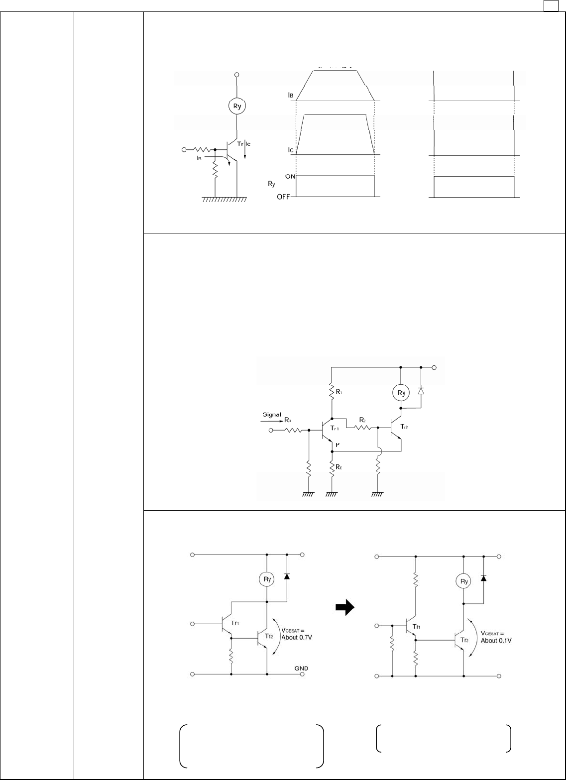
3. Snap action (Characteristic of relay with voltage rise and fall)
It is necessary for the relay coil not to impress voltage slowly but to impress the rated voltage in a short
time and also to drop the voltage to zero in a short time.
4. Schmitt circuit (Snap action circuit) (Wave shaping circuit)
When the input signal does not produce a snap action, ordinarily a Schmitt trigger circuit is used to
produce safe snap action.
1. The common emitter resistor R
E
must have a sufficiently small value compared with the resistance of
the relay coil.
2. Due to the relay coil current, the difference in the voltage between at point P when T
2
is conducting and
at point P when T
1
is conducting creates hysteresis in the detection capability of Schmitt circuit, and care
must be taken in setting the values.
3. When there is chattering in the input signal because of waveform oscillation, an CR time constant
circuit should be inserted in the stage before the Schmitt trigger circuit. (However, the response speed
drops.)
6. Coil
impressed
circuit
1. Relay drive
by means of
a transistor
5. Avoid Darlington circuit connections. (High amplification)
Care must be taken in this circuit due to increase of V
CESAT
. It does not cause a failure immediately, but it
may lead to troubles by using for a long period or by operating with many units.
(No good) Darlington connection
Due to excessive consumption of
power, heat is generated.
A strong Tr1 is necessary.
(Good) Emitter connection
Tr2 conducts completely.
Tr1 is sufficient for signal use.
(No good) Without snap action (Good) Snap action
Non-pulse signal
Pulse signal (square wave)


