8
1. Relay drive
by means of
a transistor
6. Residual Coil Voltage
In switching applications where a semiconductor (transistor, UJT, etc.) is connected to the coil, a residual
voltage is retained at the relay coil which may cause incomplete restoration and faulty operation. Using
of DC coils may cause incomplete restoration or reduction in contact pressure and vibration resistance,
because its drop-out voltage is lower than that of AC coil (10% or more of the rated voltage) also
because there is a tendency to increase the life by lowering the drop-out voltage.
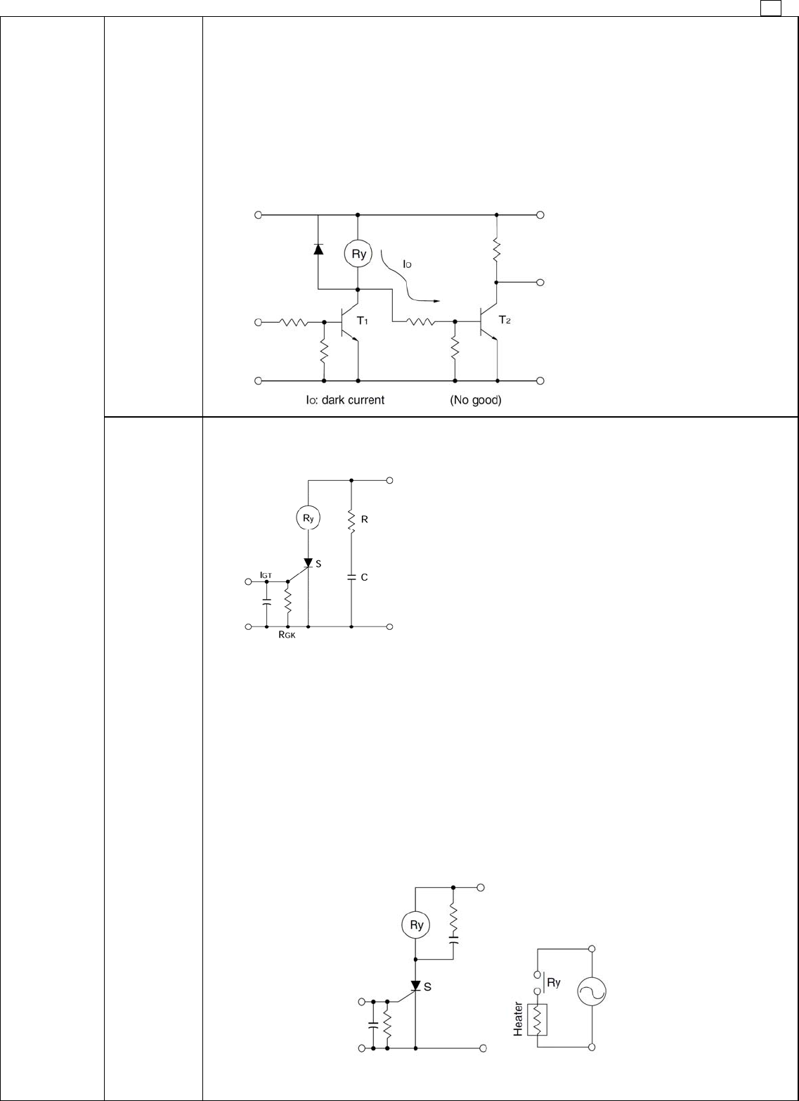
When the signal from the transistor's collector is taken and used to drive another circuit as shown in the
figure as follows, a minute dark current flows to the relay even if the transistor is off. This may also cause
the problems described above.
Connection to the next stage through collector
6. Coil
impressed
circuit
2. Relay drive
by means of
SCR
1. Ordinary drive method
For SCR drive, it is necessary to take particular care with regard to gate sensitivity and erroneous
operation due to noise.
2. Cautions regarding ON/OFF control circuits
(when used for temperature control circuits or similar one)
Care must be taken because the electrical life suffers extreme shortening when the relay contacts close
simultaneously with an AC single phase power source.
1. When the relay is turned ON and OFF using a SCR, the SCR serves as a half wave power source as it
is, and there are ample cases where the SCR is easily restored.
2. In this manner the relay operation and restoration timing are easily synchronized with the power
source frequency, and the timing of the load switching also is easily synchronized.
3. In case of the load for temperature control whose load is a high current load such as a heater, some
relays switch only peak values and some other relays switch only zero phase values as a phenomenon
of this type of control. (Depending upon the sensitivity and response speed of the relay)
4. Accordingly, it causes either an extremely long life or an extremely short life resulting in wide variation.
So, it is necessary to take care with the initial device quality check.
I
GT
: There is no problem even with more than 3 times
the rated current.
R
GK
: 1K ohms must be connected.
RC : This is for prevention of switching error due to a
sudden rise in the power source or to noise.


