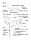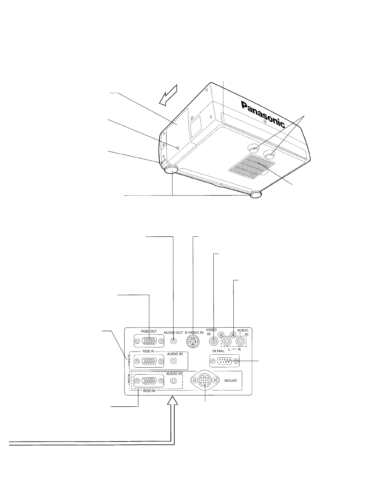
<Back, bottom and right view>
Remote control signal receptor (page 10)
This receives the infrared signal transmissions from the
remote control unit.
Lamp unit cover
(page 42)
Remove this cover to get access
to the lamp unit.
Front
Fixing screw for the lamp
unit cover
(page 42)
Remove this screw when
replacing the lamp unit.
Adjuster button
(page 15)
This button is used to
unlock the adjustable legs.
Adjustable legs (two)
(page 15)
These legs can be used to adjust
the angle of inclination of the
projector.
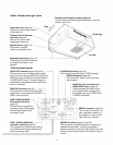
<Side terminal board>
AUDIO OUT terminal
(pages 33 and 34)
This terminal is used to output audio signals
which are input from the AUDIO IN terminal for
RGB input or the AUDIO IN (L-R) terminals for
S-VIDEO/VIDEO input. The sound output is
automatically switched when the audio input
source is switched.
RGB OUT terminal
(page 34)
This terminal is used to output the RGB
signal which is connected to the RGB 1 or
RGB 2 input connector.
RGB 2 (RGB IN/AUDIO
IN) connector/terminal
(page 34)
This connector and terminal
are used to input RGB signals
and the audio signal which
accompany them.
RGB 1 (RGB IN/AUDIO IN)
connector /terminal
(page 34)
This connector and terminal are used to
input RGB signals and the audio signal
which accompany them.
Fixed legs
Air filter
S-VIDEO IN terminal
(page 33)
This terminal is used to input S-VIDEO signals.
VIDEO IN terminal
(page 33)
This terminal is used to input composite
video signals.
AUDIO IN (L-R) terminals for S-
VIDEO/VIDEO input
(page 33)
These terminals are used to input
audio signals which correspond to
the signals input to the VIDEO IN or
S-VIDEO IN terminal.
SERIAL connector
(page 36)
This connector is used to con-
nect a personal computer to
the projector in order to exter-
nally control the projector.
MOUSE connector
(pages 34 and 35)
This connector is used to connect an accessory or
separate mouse cable. This lets you operate a
personal computer using the pointer button and click
buttons on the remote control unit instead of using a
mouse.
8


