10
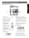
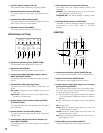
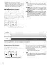
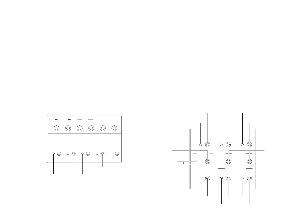
!0 Auxiliary Speaker Volume (AUX, SP)
This control sets the output level of auxiliary speaker.
!1 Auxiliary Microphone Volume (AUX, MIC)
This control sets the input level of gooseneck micro-
phone.
!2 Vehicle Detector Beep Volume (BEEP)
This control sets the vehicle detection beep tone for the
Order Taker or the All-in-One Headset.
!3 POS Audio Volume (POS AUDIO)
This control sets the input level of POS audio.
[OPERATIONAL SETTING]
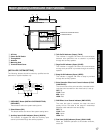
!4 Speed Team Indicator (yellow) (SPEED TEAM)
This indicates that the speed team mode is on.
!5 Speed Team On/Off Button
This button turns the speed team mode on and off.
!6 Vehicle Detector Beep Day/Night Indicator (yellow)
(BEEP DAY/NIGHT ON:DAY)
This indicates that the vehicle detector beep has select-
ed DAY.
!7 Vehicle Detector Beep Day/Night Button
This button turns the vehicle detector beep DAY and
NIGHT.
Day mode: Disables the vehicle detector beep on the
other lane.
Night mode: Reduces the volume of the vehicle detec-
tor beep on the other lane.
!8 Outside Speaker Level Indicator (yellow) (OUTSIDE
SP LEVEL ON:DAY)
This indicates that the outside speaker level has select-
ed normal level.
!9 Outside Speaker Level DAY/NIGHT Button
This button turns the outside speaker level normal level
and 50% level.
@0 Vehicle Detector Normal/Override On Indicator (yel-
low) (V/DET OVERRIDE)
This indicates that the vehicle detector has selected
Override On.
@1 Vehicle Detector Normal/Override On Button
This button turns the vehicle detector Normal and
Override On.
NORMAL: The vehicle detector turns on only when vehi-
cle is detected at the menu board.
OVERRIDE ON: The vehicle detector is always turned
on.
@2 Talk/Page Release Button (T/P RELEASE)
The button is used to release temporarily the talk/page
communication of the Order Taker or All-in-One
Headset.
[GREETER]
@3 Greeter On/Off Indicator (yellow) (GREETER, ON)
This indicates that the greeter function has selected on.
@4 Greeter On/Off Button (GREETER, ON)
This button turns the greeter function on and off.
@5 Greeter Memory Select and Output Level Indicator
(green/yellow/red) (SELECT)
This indicates that the greeter memory has been select-
ed. Each memory has a capacity to record a message
for 16 seconds at the maximum.
1: This indicates that the greeter memory has selected
1. (The message of “Please pull forward” is a factory
default.)
2: This indicates that the greeter memory has selected
2.
Off: Greeter is Off.
Green: When the greeter output level set in LOW, the
indicator lights up in green.
Yellow: When the greeter output level set in MID, the
indicator lights up in yellow.
Red: When the greeter output level set in HIGH, the indi-
cator lights up in red.
@6 Greeter Memory Select Button (SELECT)
This button selects either of the greeter memories.
OPERATIONAL SETTING
OUTSIDE
SPEED
TEAM
BEEP
DAY/NIGHT
ON:DAY
OUTSIDE
SP LEVEL
ON:DAY
V/DET
OVERRIDE
T/P
RELEASE
SP
MIC
SP
MIC
AUX
BEEP
POS
AUDIO
!5 !7 !9 @1 @2
!4 !6 !8 @0
GREETER
START
DELAY
ON
DOWN
UP
1
2
REC
SELECT
VOLUME
DESTINATION
AUX
HEADSET
HEADSET
PLAYBACK
@
4
@9
@3
@8
@7
#4
#5
#
3
#
6
#2
#0
#1
@5
@6


