


19
Installations/Connections
■ Installation procedures
Preparations (Refer to page 19.)
Installation of center modules on the wall (Refer to page 19.)
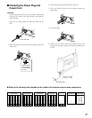
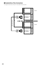
Wiring to the center modules (Refer to page 20.)
ID registration for follower units (Refer to page 25.)
[System Setup]
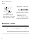
Installed System Setting
(Refer to page 26.)
Adjustments to adequate sound levels
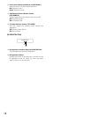
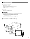
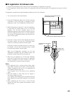
■ Preparations
This Center Module is designed to be mounted on a wall directly. Please be advised of the following:
• Procure 4 mounting screws according to the material of the installation area.
In this case, wood screws and nails should not be used.
Recommended screw: M4 x 25 mm
• Required pull-out capacity of a single screw/bolt is 118 N {12 kgf} or more.
• If a wall board is too weak to support the total weight, the area shall be sufficiently reinforced.
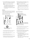
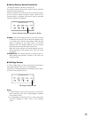
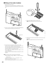
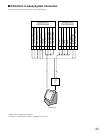
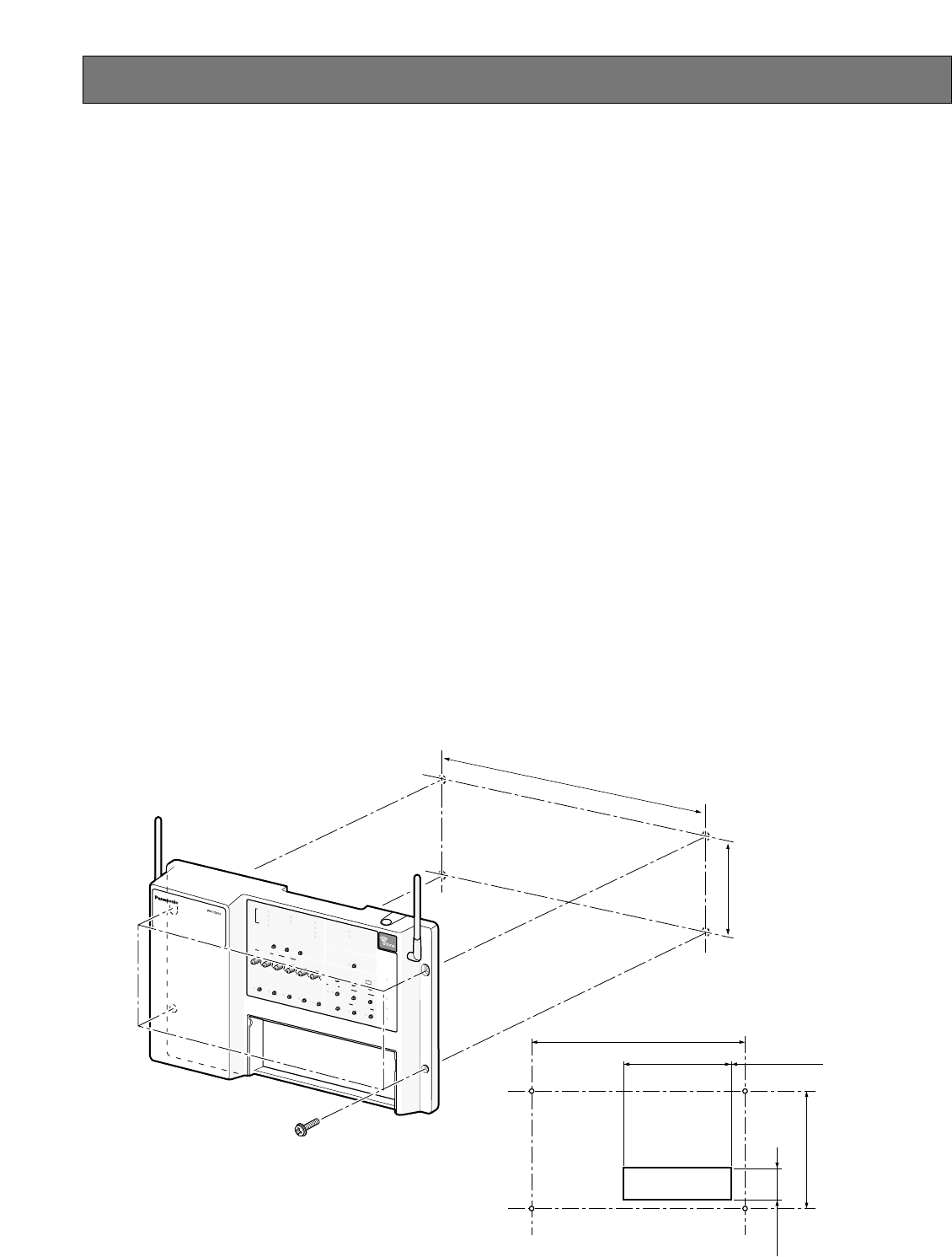
■ Installation of center modules on the wall
Fix the center module directly to the wall, using the prepared 4 screws. (These screws are not furnished.)
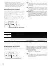
INSTALL SYSTEM S
ETTING
OPERATIONAL SETTING
ID REGISTRATION
GREETER
POW
ER
TELEP
HONE
CONTROL OUT
START
DELAY
ON
DOWN
PREV
ECHO CANCELLER
D
NR LEVEL
DUAL LANE
LANE SELECT
POS REMOTE
TX
POWER
R
ED MAX
YELLOW
MD
GR
EEN LOW
OFF OFF
SEL
AUX
SP
AUX IN
TALK
PAGE
BEEP
NEX
T
OUTSID
E
SP
EED
TEAM
BEEP
DAY/NIGHT
ON:DAY
OUTSIDE
SP LEVEL
ON:DAY
V/DET
O
V
ERRIDE
T
/P
PRELEASE
S
P
MIC
SP
MIC
AU
X
B
EEP
POS
AUDIO
UP
1
2
REC
TALK
PAGE
VE
HICLE
DETE
C
TOR
SELECT
VOLUME
DESTINATI
ON
AU
X
HEA
DSET
HEADSET
PLAYBACK
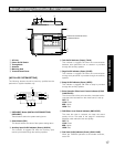
386 mm {15-1/4"}
150 mm {15-7/8"}
20 mm
{3/4"}
60 mm
{2-3/8"}
150 mm {5-7/8"}
225 mm {8-7/8"}
386 mm {15-1/4"}
25 mm {1"}
Use the dents at the top or bottom of
center module for wiring. When routing
wires through the wall, make the
openings according to the dimensions
in this illustration.