1752 and 1754 SHDSL Router User’s Guide
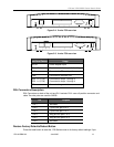
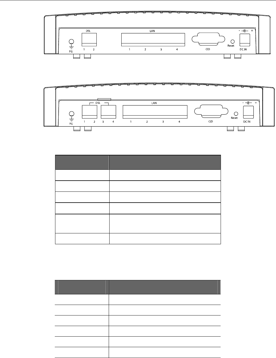
Figure 2-4. 2-wire 1752 rear view
Figure 2-3. 4-wire 1754 rear view
Back Panel Feature Usage
DC IN Power Adapter Input
Reset Button Reset device to factory default setting
CID Connected to PC serial port for console
LAN Connected to Ethernet Port
DSL 1–2 (1752)
DSL 1–4 (1754)
Connected to loops 1 through 2
Connected to loops 1 through 4
FG Connected to ground wire
DSL Connectors Description
DSL Connectors on back of the unit are RJ11 sockets. RJ11 uses a 6-position connector and
cable. Two wire pairs are used for SHDSL.
Pin Purpose
Pin 1 Not used.
Pin 2 Tip for DSL pair 2 or 4.
Pin 3 Tip for DSL pair 1 or 3
Pin 4 Ring for DSL pair 1 or 3
Pin 5 Ring for DSL pair 2 or 4
Pin 6 Not used.
Restore Factory Defaults/Reboot Button
Press the reset button to reset the 1750 Series router to its factory default settings. If you
1752-A2-GB20-00 June 2005 13


