Table of Contents
v3000-A2-GA31-80 December 1994
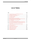
List of Tables
Table Page
1-1 Technical Specifications for the COMSPHERE 3000 Series Carrier 1-3. . . . . . . . . . . .
3-1 Fan Module Cooling Requirements 3-15. . . . . . . . . . . . . . . . . . . . . . . . . . . . . . . . . . . . . .
3-2 Shared Diagnostic Control Panel Status Indicators 3-17. . . . . . . . . . . . . . . . . . . . . . . . . .
3-3 Shared Diagnostic Unit Status Indicators 3-23. . . . . . . . . . . . . . . . . . . . . . . . . . . . . . . . .
3-4 Carrier Address DIP Switches 3-24. . . . . . . . . . . . . . . . . . . . . . . . . . . . . . . . . . . . . . . . . .
3-5 Carrier Address Assignment 3-25. . . . . . . . . . . . . . . . . . . . . . . . . . . . . . . . . . . . . . . . . . .
3-6 Protocol DIP Switches 3-25. . . . . . . . . . . . . . . . . . . . . . . . . . . . . . . . . . . . . . . . . . . . . . . .
A-1 Digital or Analog Leased-Line Network Interface A-2. . . . . . . . . . . . . . . . . . . . . . . . . .
A-2 RJ21X (Permissive) Dial and 2-Wire Switched 56 Network Interface Module A-2. . . .
A-3 RJ27X (Programmable) Dial Network Interface Module A-3. . . . . . . . . . . . . . . . . . . . .
A-4 SJA57 4-Wire Switched 56 Network Interface Module A-3. . . . . . . . . . . . . . . . . . . . . .
A-5 SDU – NMS Interface A-4. . . . . . . . . . . . . . . . . . . . . . . . . . . . . . . . . . . . . . . . . . . . . . . .
A-6 SDU – Shared Diagnostic Control Panel Interface A-4. . . . . . . . . . . . . . . . . . . . . . . . . .
A-7 Pinout for 3600-F2-503 (Digital and JM8 Leased) Network Interface Cables A-5. . . . .
A-8 Pinout for 3600-F2-504 (Dial Programmable – RJ45S) Network Interface Cable A-6. .
A-9 Pinout for 3600-F1-505 (Dial Permissive – RJ11C) Network Interface Cable A-7. . . . .
A-10 Pinout for 3000-F1-009 (50-Pin to Eight 6-Pin Modular) Network
Interface Cable A-8. . . . . . . . . . . . . . . . . . . . . . . . . . . . . . . . . . . . . . . . . . . . . . . . . . . .
A-11 Connectors on the COMSPHERE 3000 Series Carrier’s Backplane A-9. . . . . . . . . . . . .
A-12 D-Lead Control Interface A-10. . . . . . . . . . . . . . . . . . . . . . . . . . . . . . . . . . . . . . . . . . . . . .
B-1 Auxiliary Backplane Connectors B-3. . . . . . . . . . . . . . . . . . . . . . . . . . . . . . . . . . . . . . . .
B-2 T1 Network Interface Connector (RJ48H) B-6. . . . . . . . . . . . . . . . . . . . . . . . . . . . . . . .
B-3 DTE (DSX-1) Interface Connector (J3) B-7. . . . . . . . . . . . . . . . . . . . . . . . . . . . . . . . . . .
B-4 COM Port Adapter Connector (J6) B-10. . . . . . . . . . . . . . . . . . . . . . . . . . . . . . . . . . . . . .
B-5 EIA-530A Port Interface Connector B-11. . . . . . . . . . . . . . . . . . . . . . . . . . . . . . . . . . . . .
B-6 RS449 Port Interface Connector B-12. . . . . . . . . . . . . . . . . . . . . . . . . . . . . . . . . . . . . . . .
B-7 V.35 Port Interface Connectors B-14. . . . . . . . . . . . . . . . . . . . . . . . . . . . . . . . . . . . . . . . .
B-8 External Clock Connector B-16. . . . . . . . . . . . . . . . . . . . . . . . . . . . . . . . . . . . . . . . . . . . .


