Installation
3-273000-A2-GA31-80 December 1994
NMS Connection
A COMSPHERE 3000 Series Carrier can be connected
to a variety of Network Management Systems (6800
Series NMS, 6700 Series NMS, DATAPHONE II Level 4
System Controller, DATAPHONE II Diagnostic Console,
DATAPHONE II Network Controller, and ANALYSIS
6510 NMS) via the control channel interface on the SDU,
but all 16 slots in the carrier can only be controlled by one
Network Management System. One control channel can
manage up to eight COMSPHERE 3000 Series Carriers
by daisy chaining from the CC IN) to the CC OUT
interfaces on the SDU in each carrier.
NOTE
You cannot use the NMS
connected through the SDU with
either Model 3151 CSUs or 3161
DSU/CSUs.
The types of NMS that can connect to the
COMSPHERE 3000 Series Carrier have a variety of
physical and electrical interfaces. The control channel
CC IN interface on the SDU, where the NMS is
connected to the COMSPHERE 3000 Series Carrier, is a
6-pin modular jack. For each type of NMS, a specific
adapter is required to convert the control channel interface
from the NMS to the 6-pin modular plug required for the
SDU. The adapters required are described below.
• The COMSPHERE 6800 Series NMS, 6700 Series
NMS, ANALYSIS 6510 NMS, and later releases of
the DATAPHONE II Level 4 System Controller use
a 25-pin EIA-232 interface and a gender adapter.
The 25-pin to 6-pin adapter for a central site is
AT&T Paradyne feature number 4400-F1-594; for
the remote site, it is 6821-F1-518. The ANALYSIS
gender adapter is AT&T Paradyne part number
4951-031. In addition, a 6-conductor cord with
6-pin plugs on each end can be used to make this
connection. This cord is AT&T Paradyne feature
number 4400-F1-510 (3 feet).
You can also connect a remote NMS to a
COMSPHERE 3000 Series Carrier via a Modular
3551, 3611, or 3616 DSU and an NMS adapter
cable (feature number 3000-F2-510). For
information on how to install the NMS adapter
cable, refer to the appropriate user documentation.
• The DATAPHONE II Diagnostic Console, Network
Controller, and older releases of a Level 4 System
Controller use a 10-pin interface for the Control
Channel. The 10-pin to 6-pin cable is AT&T
Paradyne feature number 4400-F1-577 (5 feet). Use
this adapter when the DSUs in the carrier are
controls on the backbone network.
To connect the local NMS to the COMSPHERE 3000
Series Carrier:
Procedure
1. Obtain the correct adapter, as described above, and
connect it to the network management port on the
NMS device (on the COMSPHERE and
DATAPHONE II systems, the port is labeled
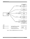
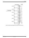
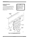
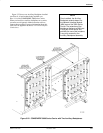
CC OUT or DC OUT). (See Figure 3-17 for an
NMS to a COMSPHERE 3000 Series Carrier
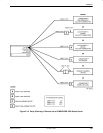
connection, Figure 3-18 for a diagnostic channel
daisy chain of devices into a COMSPHERE 3000
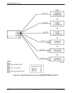
Series Carrier, and Figure 3-19 for a diagnostic
channel daisy chain of devices from a
COMSPHERE 3000 Series Carrier.)
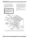
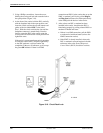
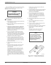
2. Use a 6-pin modular telephone cord to connect the
modular side of the adapter to the CC IN jack on
the rear of the SDU in the COMSPHERE 3000
Series Carrier (Figure 3-20).
3. For a cabinet configuration with multiple carriers,
connect all of the SDUs in a daisy chain, starting
with the SDU connected to the NMS. Use a 6-pin
modular telephone cord to connect the CC OUT
jack at the rear of this SDU to the CC IN jack of
the SDU in the next carrier above or below it. Use
another cord to connect the second SDU’s
CC OUT jack to the next SDU’s CC IN. Continue
to the last carrier in the cabinet.
4. After at least one DSU has been installed in the
carrier, check that the SDU is functioning properly
by polling the DSUs for health and status.


