Installation
3-33000-A2-GA31-80 December 1994
There are nine NIMs available. The following NIMs
are used with the 3600 Series DSUs/DBMs:
• Permissive NIM (for use with V.32 and 2-wire
Switched 56 DBMs)
• Programmable NIM (for use with V.32 DBMs)
• 4-wire Switched 56 NIM (for use with 4-wire
Switched 56 DBMs)
WARNING
Do not connect a 2-wire
switched 56 kbps plug into an
RJ11C jack. This type of jack is
intended for analog PSTN
devices. Failure to do this may
cause equipment damage and
harm to the telephone network.
The following NIMs are used with the dial/lease
modems, or a combination of DSUs with V.32 DBMs and
dial/lease modems in the same carrier half:
• Permissive NIM (3911 only)
• Permissive NIM with the Make Busy feature
• Programmable NIM with the Make Busy feature
(3811 only)
• Permissive NIM with the Service Line feature
• Programmable NIM with the Service Line feature
(3811 only)
• Permissive NIM with both the Make Busy and
Service Line features
• Programmable NIM with both the Make Busy and
Service Line features (3811 only)
NOTE
You cannot use a NIM on the side of
the carrier where an Auxiliary
Backplane is installed.
Programmable mode corrects any loss in the transmit
signal level between the modem and the central office by
permitting the modem to transmit at the optimum signal
level. This is accomplished by the local telephone
company installing a resistor into the network interface
and is usually identified by an RJ45S-type jack.
Permissive mode is a standard dial-line connection and
is identified by the use of an RJ11C- or SJA48-type jack.
(The carrier also supports RJ21X- and RJ27X-type mass
termination interfaces for Permissive and Programmable
modes, respectively.)
The DDD NIMs, programmable and permissive, may
have Make Busy and Service Line as additional
capabilities. The Make Busy feature is useful when
modems are used in a ‘‘hunt” or ‘‘rotary” group. This
feature ties the Tip and Ring signals together so that the
modem appears busy. Make Busy is not used by DSUs
with DBMs, but using a NIM with this feature will not
affect the DBM’s performance. The Service Line feature
permits an extra dial line to be connected to a
COMSPHERE 3000 Series Carrier. NIMs with this
feature are identified by the two modular connectors
mounted on the NIM.
WARNING
The Make Busy feature must
only be used behind a PBX.
Connecting a NIM with the Make
Busy capability directly to the
PSTN is a violation of FCC
Part 68 Rules and Canadian
DOC CS-03 Regulations.
Non-modular DSUs equipped with TDM or MCMP
circuit cards are supplied with time division multiplexer
interface cables. If you plan to use the digital bridge
function, you must order a digital bridge interface cable.
When modular DSUs or modems are to be installed in
the carrier, rear connector plates or connector modules
must be installed at the rear of the carrier. Modular DSUs
and dial/lease modems are circuit cards that can be
removed from the front of the carrier without disturbing
the DTE cables attached to the rear connector plate at the
rear of the carrier. Also, there are connector modules that
are supplied with the modular DSU-TDM (or
DSU-MCMP) circuit cards. These connector plates and
modules function as interfaces between the modular
circuit cards and the DTEs.
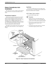
A power transformer unit provides low voltage
ac power to the carrier’s internal power distribution bus.
A carrier designed to operate from a –48 Vdc power unit
is also available. This power unit is called the Central
Office (CO) Power Unit and it consists of one dc power
module. Note that an optional second power module is
available. For more information on the CO Power Unit,
see the COMSPHERE –48 Vdc Central Office Power
Unit, Installation Guide.


