1-13000-A2-GA31-80 December 1994
Introduction
Overview 1-1. . . . . . . . . . . . . . . . . . . . . . . . . . . . . . . . . . . . . . . . . . . . . . . . . . . . . . . . . . . . . . . . . . . . . . . . . .
Features 1-1. . . . . . . . . . . . . . . . . . . . . . . . . . . . . . . . . . . . . . . . . . . . . . . . . . . . . . . . . . . . . . . . . . . . . . . . . . .
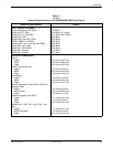
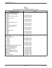
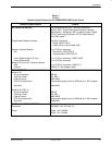
Technical Specifications 1-3. . . . . . . . . . . . . . . . . . . . . . . . . . . . . . . . . . . . . . . . . . . . . . . . . . . . . . . . . . . . . .
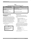
Equipment Warranty and Support 1-8. . . . . . . . . . . . . . . . . . . . . . . . . . . . . . . . . . . . . . . . . . . . . . . . . . . . . .
Equipment Service 1-8. . . . . . . . . . . . . . . . . . . . . . . . . . . . . . . . . . . . . . . . . . . . . . . . . . . . . . . . . . . . . . .
Out of Warranty 1-9. . . . . . . . . . . . . . . . . . . . . . . . . . . . . . . . . . . . . . . . . . . . . . . . . . . . . . . . . . . . . . .
Enhanced Support Services 1-9. . . . . . . . . . . . . . . . . . . . . . . . . . . . . . . . . . . . . . . . . . . . . . . . . . . . . . . . .
Overview
AT&T Paradyne offers the COMSPHERE
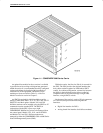
3000 Series Carrier, Figure 1-1, assembly to support
high-density mounting of the following AT&T Paradyne
products in a central-site environment:
• Model 3151 Channel Service Units (T1 CSUs)
• Model 3161 Data Service Units/Channel Service
Units (T1 DSU/CSUs)
• Models 3511, 3551, 3611, and 3616 Data Service
Units (DSUs)
• Models 3811 and 3911 dial/lease modems
Features
The carrier provides a convenient assembly in which
you can install a combination of up to 16 T1 CSUs, T1
DSU/CSUs, DSUs, and/or dial/lease modems in a
space-efficient package for crowded computer/
communications room environments.
In addition to the 16 devices, a single carrier operates
with a power transformer unit, an optional fan module, an
optional Shared Diagnostic Control Panel (SDCP), and an
optional speaker panel (for use with Models 3811 and
3911 dial/lease modems only).
The number of devices that can be installed in a carrier
is reduced by one for each Time Division Multiplexer
(TDM) or Multichannel Multipoint (MCMP) circuit card
that is installed. A TDM or MCMP card (functioning as a
multiplexer or digital bridge) is physically attached to a
Model 3611 DSU and occupies a separate slot in the
carrier. For digital bridge applications, each DBM-V,
DBM-S, or DBM-D occupies a separate slot, as well.
The ac power distribution systems for the carrier
consist of a power transformer unit that contains two
transformers, each serving eight slots in the carrier. The
backplane distributes low-voltage ac power from the
transformers to each slot, and an individual power supply
on each DSU or dial/lease modem produces the regulated
dc voltage.
A carrier designed to operate from a –48 Vdc power
unit is also available. This unit, called the Central Office
(CO) Power Unit, consists of a single dc power module
with a fan and operates in Basic mode (the mode of
operation in which the single power module supplies
power to the entire carrier). An optional second power
module is available for the CO Power Unit. With the
optional second power module, the CO Power Unit can be
configured to operate in either the Redundant mode (the
mode of operation in which both power modules serve all
the slots in the carrier and if one power module fails, the
remaining power module assumes the entire load) or the
Independent mode (the mode of operation in which each
power module serves only eight consecutive slots –
Slots 1 through 8 or Slots 9 through 16 in the carrier). The
Shared Diagnostic Unit (SDU), which is contained in
Slot 0, is powered by both power modules. For more
information, see the COMSPHERE –48 Vdc Central
Office Power Unit Installation Guide.
1


