COMSPHERE 3000 Series Carrier
3-12 December 1994 3000-A2-GA31-80
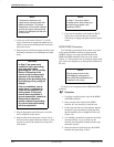
NOTE
The power transformer unit
output wires are terminated with
plastic connectors. The power
transformer unit must be installed
so that the output wires protrude
through the backplane at the rear
of the carrier.
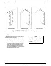
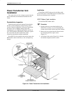
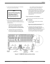
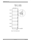
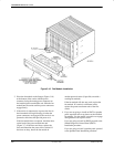
3. At the rear of the carrier (Figure 3-7), use the
larger screwdriver to engage and tighten the two
captive screws that fasten the power transformer
unit to the carrier.
4. Plug the power transformer output connectors into
the mating connectors on the backplane and latch
them.
CAUTION
In Step 5, the power cord
contains a 3-wire grounding-
type plug which has a
grounding pin. This is a safety
feature. Grounding of the
carrier is vital to ensure safe
operation. Do not defeat the
purpose of the grounding plug
by modifying it or by using an
adapter.
Prior to installation, use an
outlet tester or voltmeter to
check the ac receptacle for
earth ground. If the power
source does not provide a
ground connection, consult an
electrician to determine
another method of grounding
the carrier before proceeding
with the installation.
5. Plug the appropriate end of the power cord into
the ac receptacle on the carrier.
6. Plug the other end of the power cord into one of
the convenience outlets inside the cabinet, or to an
external ac outlet if the cabinet does not provide
other outlets.
NOTE
In Step 7, the cover plate is
installed at this time unless you
are planning to install a fan
module or SDCP.
7. If you are not installing a fan module or SDCP,
replace the cover plate, then use the smaller
screwdriver to engage and tighten the four captive
screws.
SGRD/FGRD Connection
If all the DSUs and modems in the carrier are to have
frame ground (FGRD) connected to signal ground
(SGRD), install a wire strap (provided) between the
SGRD and FGRD terminals at the rear of the carrier
(Figure 3-7). The terminals are an insulation displacement
type, with a slot designed to cut through the insulation on
the wire.
NOTE
Signal ground must not be
connected to frame ground
when 3900 Series Modems are
installed in the carrier.
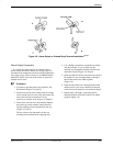
To install a wire strap between the SGRD and FGRD
terminals:
Procedure
1. Use pliers to pull the plastic caps off the SGRD
and FGRD terminals.
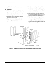
2. Insert one end of the strap into the SGRD
terminal. It is not necessary to strip the wire.
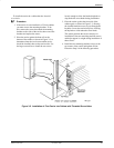
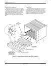
3. Fit the strap into the slot in the terminal. Replace
the plastic cap on the terminal, fitting the strap
into the matching slot cut lengthwise in the cap
(Figure 3-8).
4. Use a Phillips screwdriver to push the cap firmly
onto the terminal. As you seat the cap, the
terminal cuts through the insulation on the strap
and makes contact.
5. Insert the other end of the strap into the FGRD
terminal and repeat Steps 3 and 4.


