Installation
3-53000-A2-GA31-80 December 1994
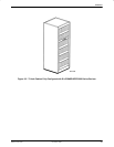
Cabinet Setup
The cabinet is shipped from the factory with doors,
mounting rails, and two factory-installed ac power strips.
Cabinet setup requirements are, therefore, minimal and
consist of leveling the cabinet once it is in place at your
site and, if needed, reversing the cabinet doors.
Leveling the Cabinet
There are four adjustable leveling screw feet at the
bottom of the cabinet; these screw up or down, enabling
you to adjust the cabinet to a level position on the floor.
You can use a level if desired, and you will need an
adjustable crescent wrench to rotate the feet to level the
cabinet.
To level the cabinet:
Procedure
1. Place the level against the front door and adjust
the leveling feet until the cabinet stands level
vertically from front to rear.
2. Place the level against one cabinet side and adjust
the leveling screws until the cabinet stands level
vertically from side to side.
Reversing the Cabinet Doors
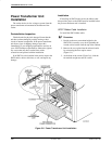
The cabinet’s front and back hinged doors are installed
on the cabinet frame at the factory to open left-to-right.
You can use pre-drilled holes on the opposite side of the
frame to reverse the door, allowing the door to open
right-to-left.
To reverse a door:
Procedure
1. Supporting the door, use a flat-blade screwdriver
to remove the screws from the bottom hinge,
detaching the hinge from the cabinet frame.
2. Supporting the door, remove the screws from the
top hinge, detaching the hinge and the door from
the cabinet frame.
3. Flip the door end-over-end.
4. Holding the door in position on the opposite side,
align the hinge holes with the predrilled holes on
the cabinet frame provided for this purpose. Then
use the same screws to reattach the door by its
hinges to the cabinet.
Carrier Installation
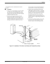
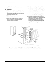
You will need a large, Phillips screwdriver to install the
carrier in the cabinet and to install the power transformer
unit under the carrier. A small, flat-blade screwdriver is
required to remove and replace the cover plate or SDCP,
and to install the 50-pin cable connectors.
Each carrier is shipped with the following associated
equipment:
• Six cable ties
• Two fuses (spares)
• Four #10-32 mounting screws
• Four cabinet (4000-B2-200) #12-24 mounting
screws and four speed nuts for use with other
cabinets
• One jumper wire for the frame ground/signal
ground
These items are bundled together in a plastic bag.
The carrier and its associated auxiliary equipment are
designed to be mounted in cabinets.
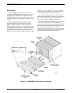
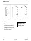
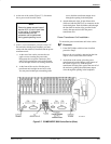
The carrier is equipped with reversible mounting
brackets (Figure 3-2) to allow installation in cabinets that
are either 19 inches or 23 inches wide. These brackets are
initially positioned to allow the carrier to be installed in a
cabinet on 19-inch centers.
Preinstallation Inspection
Remove the carrier from its shipping container and
check for physical damage. If the carrier shows signs of
shipping damage, report this immediately to your shipping
representative and also to your AT&T Paradyne
representative. Otherwise, proceed with the installation.
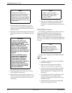
The COMSPHERE 3000 Series Carrier, Figure 3-1, is
designed to house T1 CSUs, T1 DSU/CSUs, DSUs,
DBM-Vs, DBM-Ss, DBM-Ds, TDMs, MCMPs, and
dial/lease modems. The carrier is a metal enclosure that
contains slots for installation of 17 circuit cards. The slot
labeled SDU (Slot 0) is reserved for the Shared Diagnostic
Unit (SDU); Slots 1 through 16 are for T1 CSUs, T1
DSU/CSUs, DSUs, DBM-Vs, DBM-Ss, DBM-Ds, TDMs,
MCMPs, or dial/lease modems. Under each slot number
(on the cover plate or SDCP) is a small area in which to
write the circuit channel identification numbers.


