


Index
IN-3
7975-A2-GB20-40 December 1998
M
main menu, 2-2, A-1
Management and Communication Options, A-11
management port
access, 7-1
settings, 2-1
Margin Threshold, A-2
Memory Fail, status, 4-4
messages
alarm and device, 6-1
health and status, 4-3
line 24, 6-3
self-test results, 4-4
test status, 4-5
MIB
general support, 1-5
support, 1-5
monitoring, 4-1
N
navigating the screens, 2-6
Net Margin Threshold, status message, 4-3
network
interface options, A-2
tests, 5-2
Network DSL Failed, self-test result, 4-4
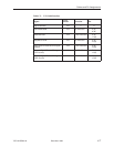
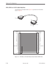
network interface, pin assignments, C-2– C-12
network interface options, A-3
Network-Initiated DCLB, A-5
NMS
SNMP access, 7-5
SNMP connectivity, 8-1
no test active status message, 4-5
O
OK, LED, 4-10
OOF (Out Of Frame), status message, 4-3
options, configuration tables, A-1
overview
8775 Termination Unit, 1-2
user’s guide, v
P
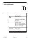
part numbers, D-1
Passed, self-test result, 4-4
Payload Rate, A-4
PC
connecting, 3-3
requirements, 3-3
Peer IP Address, A-3
performance statistics, 4-8
physical environment requirements, D-1
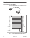
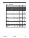
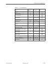
pin assignments, C-1
port, COM, C-3
Port Status, A-4
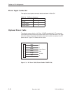
power cord installation, 3-2
power requirements, D-1
power supply
ac transformer, 3-2
optional dc, 3-2– 3-18
R
Rear Panel, 1-4
related documents, vi
remote send line loopback, 5-5
repeater loopback (RLB), 5-4
resetting
the access unit, COM port, 7-5
the unit, default configuration options, 7-5
restoring, user interface access, 7-5
RS-449 interface, C-9
S
Save Configuration screen, 3-16
saving option changes, 3-16
screen, function keys, 2-7
screens, for user interface, 2-1– 2-6
SDSL Mode, A-7
security, 7-1
Selectable Payload Rates, 3-9
self-test results, 4-4
Send and Monitor 511, 5-6
Send Ones configuration option, A-5
Send Remote DCLB Loopback, 5-10
size of unit, D-1
SNMP
trap options, 6-2
traps, B-1