


Installing the VM24 7
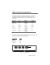
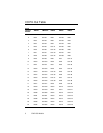
VM24 Assembly Configurations
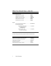
The VM24 is available in five different configurations, as shown in the
following table. Each configuration uses the same base unit. The
combination of SIM boards installed in the base unit determine the I/O
configuration.
Description P/N I/O Boards Cable Type
Single Axis
(16 IN / 8 OUT)
VM24S 2 SIM8-4X4
1 SIM8-IN
Regular
24 IN VM24IN 3 SIM8-IN Regular
24 OUT VM24OUT 3 SIM8-OUT Regular
16 IN/8 OUT VM16/8 1 SIM8-OUT
2 SIM8-IN
Split
8 IN / 16 OUT VN8/16 1 SIM8-IN
2 SIM8-OUT
Split
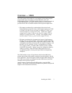
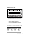
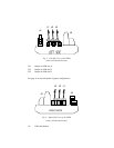
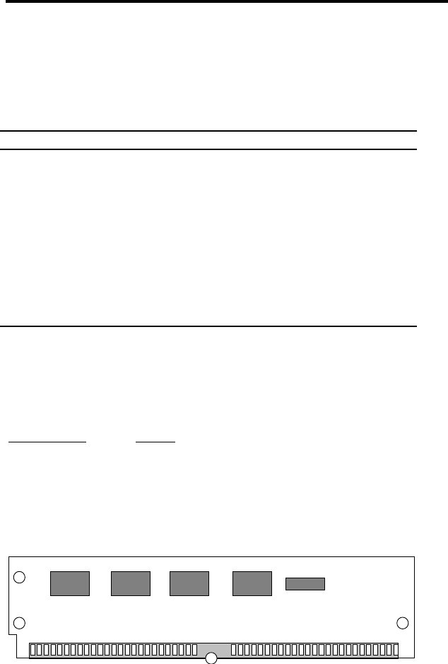
The VM24 uses Single Inline Module (SIM) style boards and sockets. The
board types are color-coded for easy identification.
Board Type Color
SIM8-IN Red
SIM8-OUT Blue
SIM8-4X4 Green
P/N: SIM8-OUT
PARKER COMPUMOTOR
Fig. 1: Typical I/O Board