


16 VM24 I/O Module
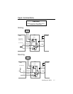
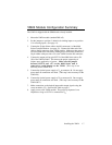
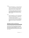
Output Connections
Caution
Remove power to the VM24 before
making any connections.
Connect the output pull-up pin OUT-P of the 6000 Series unit to V
o
on the
VM24 module to ensure the proper sequencing of output signals upon
application of power to the VM24. The Output, Ground, and +5V
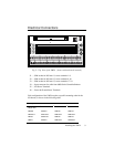
connections between the 6000 Controller and the VM24 are made with the
50-pin ribbon cable to the J4 connector.
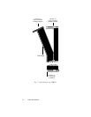
Use an external diode when driving inductive loads. Connect the diode in
parallel to the inductive load, attaching the anode to the VM24 output and
the cathode to the supply voltage of the inductive load.
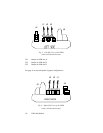
Sinking
Electronic
Device
Input
External Supply
(up to 24VDC)
+
–
VM24
6000 Series
Controller
OUT-P
+5V
Output
Connection
Ground
Connection
Iso GND
(J5)
Ground
Connection
Output
Connection
Ground
Connection
(J5)
(J6)
V
o
(J6)
(J4)
(J4)
(J4)
+5V
Iso
GND
Iso GND
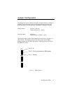
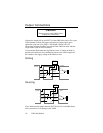
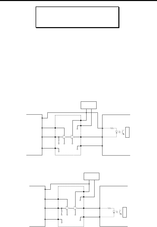
Sourcing
Electronic
Device
Input
Ground
External Supply
(up to 24VDC)
+
–
VM24
6000 Series
Controller
OUT-P
+5V
Output
Connection
Ground
Connection
Iso GND
(J5)
Ground
Connection
Output
Connection
Ground
Connection
(J5)
(J6)
V
o
(J6)
(J4)
(J4)
(J4)
+5V
Iso GND
Iso
GND
Note: Make sure the jumper between OUT-P and +5V on the 6000 Series
unit is removed to avoid damage to the VM24