


Installing the VM24 9
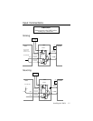
Electrical Connections
JU1
1
JU2
1
JU3
1
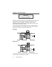
1–8
9–16
17–24
J1
J3
J4
J5
J6
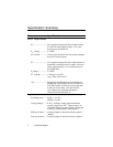
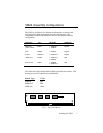
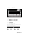
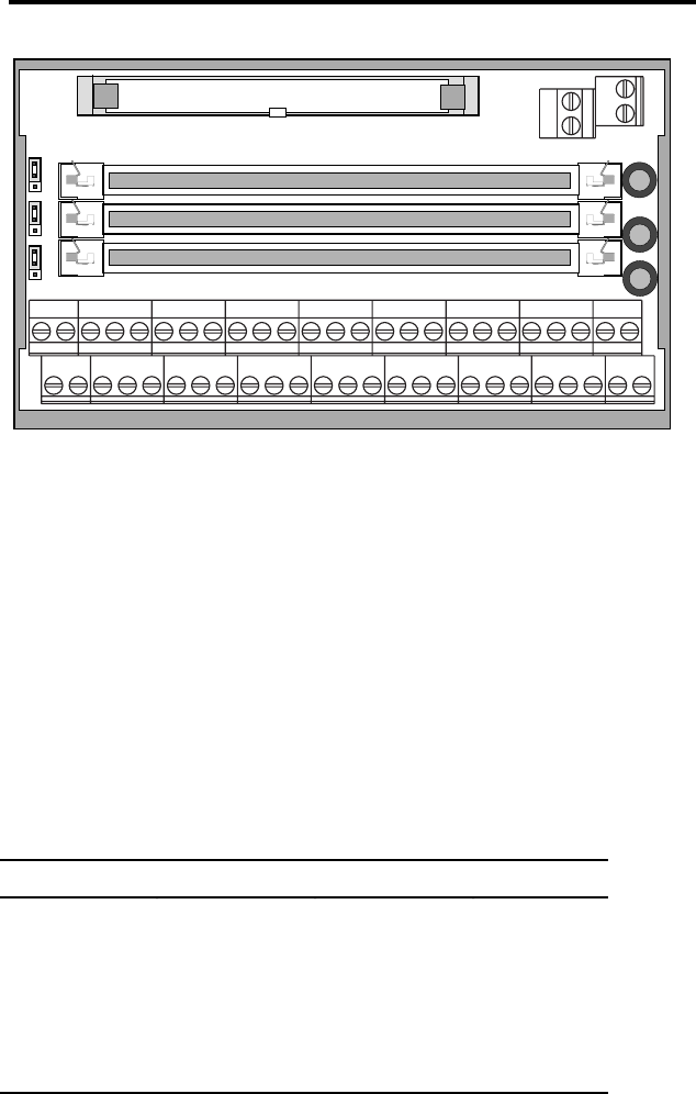
Fig. 2: Top View of the VM24 (shown without boards inserted)
J1..... SIM socket for I/O board 1, screw terminals 1-8.
J2..... SIM socket for I/O board 2, screw terminals 9-16.
J3..... SIM socket for I/O board 3, screw terminals 17-24.
J4..... Input connector for cable from 6000 Series Controller/Indexer
J5..... I/O Screw Terminals
J6..... Power & Ground Screw Terminals
Each configuration of the VM24 requires a specific mounting order for the
I/O boards, as shown in the following table:
Description J1 J2 J3
VM24S
(Single Axis)
SIM8-4x4 SIM8-4x4 SIM8-IN
VM24IN SIM8-IN SIM8-IN SIM8-IN
VM24OUT SIM8-OUT SIM8-OUT SIM8-OUT
VM16/8 SIM8-OUT SIM8-IN SIM8-IN
VM8/16 SIM8-IN SIM8-OUT SIM8-OUT