


10 VM24 I/O Module
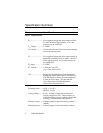
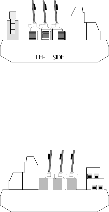
J4
J5
J1
J2
J3
JU1 JU2 JU3
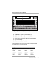
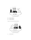
Fig. 3: Left-Side View of the VM24
(shown with boards inserted)
JU1 Jumper for SIM slot J1.
JU2 Jumper for SIM slot J2
JU3 Jumper for SIM slot J3
See page 11 for the description of jumper configurations.
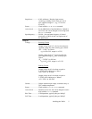
GND
V
o
V
i
RIGHT SIDE
J5
J6
J3 J2 J1
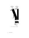
Fig. 4: Right-Side View of the VM24
(shown with boards inserted)