


4 VM24 I/O Module
Specification Summary
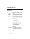
Parameter Specification
Power Requirements
V
o
........................ User-supplied voltage that drives output circuitry.
V
o
does not affect input circuitry, so it is not
necessary for the VM24-IN.
V
o
Range................ 5-24VDC
V
o
Current.............. 144mA, plus the sum of the load currents outputs
that are in sourcing mode.
V
i
.......................... User-supplied voltage that drives input circuitry &
determines switching levels for inputs. Does not
affect output circuitry, so it is not necessary for
the VM24-OUT.
V
i
Range ................ 5-24VDC
V
i
Current............... 1.5mA per volt of V
i
(e.g., 15mA for V
i
=10V)
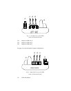
+5V....................... Supplied by the 6000 Series Controller/Indexer
through the 50-pin ribbon cable to connector J4.
The VM24 draws 0.25mA per active output and
0.5mA per active input. Also provides the
+5V output power available through the
VM24 screw terminal block J5.
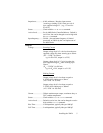
Inputs
Switching levels....... LOW ≤ 1/3 (V
i
)
HIGH ≥ 2/3 (V
i
)
Voltage Range.......... 0-24V. Voltage of input signals should not
exceed voltage level of V
i
. (Input circuitry of
VM24 has diodes to protect against voltages that
exceed V
i
, but performance may degrade.)
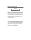
Sinking Current:....... Connect jumper for desired socket to position 3
(default)
Sourcing Current: ..... Connect jumper for desired socket to position 1