


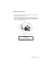

20 VM24 I/O Module
Basic Troubleshooting
When your system does not function properly (or as you expect it to
operate), the first thing that you must do is identify and isolate the problem.
When you have accomplished this, you can effectively begin to resolve the
problem.
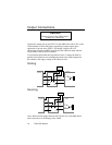
• Is the 50-pin ribbon cable connected properly to the 6000 Series
Controller / Indexer? If it's a split cable, is the input connector of the
cable connected to the input connector of the 6000 Series unit? Is the
output connector of the cable connected to the output connector of the
6000 Series unit? (See pages 12-14.)
• Is the 50-pin ribbon cable connected properly to connector J4 of the
VM24?
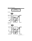
• Is the OUT-P pin on the 6000 Series Controller/Indexer connected to
V
o
? (Not applicable for the VM24-IN.)
• Is the IN-P pinon the 6000 Series Controller/Indexer connected to +5V
(or other power supply)? (Not applicable for the VM24-OUT.)
• Are the V
o
and V
i
power supplies connected to the VM24? See pages
4 and 10.
• Are the voltage values and polarities correct for V
o
and V
i
? (The
output circuitry of the SIM8-OUT and SIM8-4X4 cards are susceptible
to damage from improperly applied power. The VM24 is not short
circuit protected.)
• Are the jumpers set properly to select sinking or sourcing mode for the
inputs? (Not applicable for the VM24-OUT.) See page 11.
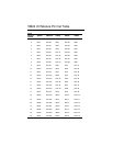
• Are the input and output devices connected to the proper inputs or
outputs on the screw terminal (J5). Verify with the I/O pin out table
on page 8.
• Is the +5V Output load limit being exceeded? (Any connections to the
+5V Output on the screw terminal [J5]? Any connection to the +5V
Output on the 6000 Series unit? See the Specification Summary on
page 6 for how to calculate the load limit.)
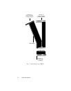
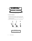
• Are the SIM8 boards installed in the proper slots? (See page 9.)
• Are the SIM8 boards seated properly in their designated slots? (See pg.
23.)