


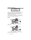

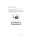

22 VM24 I/O Module
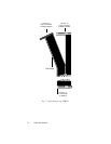
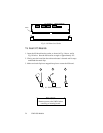
50-pin Ribbon Cable
Next, verify that the ribbon cable is relaying the signals properly. Connect
the 50-pin ribbon cable to the 6000 Series unit, but do not connect the other
end of the cable to the VM24. Repeat the above test, applying and checking
voltages at the connector that would plug into J4. (The red stripe on the
ribbon cable corresponds to pin 50 on the 6000 Series Controller/Indexer I/0
connectors.)
As an alternative, disconnect the 50-pin ribbon cable from the 6000 Series
unit and the VM24. Use a volt meter and a voltage source to verify the
continuity of the 50-pin ribbon cable.
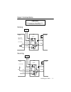
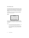
VM24
Caution
Remove power to the VM24 before
making any connections. Remember to
turn off power to the 6000 Series unit
before connecting the 50-pin ribbon
cable to the VM24. (The ribbon cable
provides +5V to the VM24 from the
6000 Series unit I/O connector.)
Once it has been verified that the 6000 Series unit and 50-pin ribbon cable
are operating properly, check the VM24 to isolate the problem. Reconnect
the 50-pin ribbon cable to the 6000 Series, and the other end to connector J4.
Turn on power.
Power
Use a volt meter to check the voltage level and polarity of V
o.
Use
a volt meter to check the voltage level and polarity of V
i.
Use a volt meter to verify the voltage level of the +5V output on
the screw terminal block (J5). (The +5V is supplied by the 6000
Series unit, and is used to power the input and output circuitry on
the SIM8 cards.)