


F • Interworking Functions Information Model 3086 G.SHDSL Integrated Access Device User Guide
176 Frame Relay Service Interworking (FRF.8)
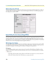
Web Configuration Methods
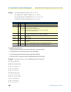
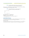
The following describes how to configure the LMI using the web interface. All LMI configuration variables are
contained under the “LMI Management” window found through the IWF link. The following image shows
the configuration variables available.
Frame Relay Service Interworking (FRF.8)
FRF.8 is a conversion mechanism by which Frame Relay networks can communicate directly with ATM-based
networks. Neither the ATM nor the Frame Relay networks require any understanding of the other network
protocols involved. This conversion is performed within the Model 3086’s IWF at the transport service level.
Frame Relay Service Interworking functions are defined by the Frame Relay Forum specification “Frame Relay/
ATM PVC Service Interworking Implementation Agreement FRF.8.1”.
FRS Configuration Options
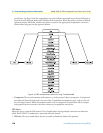
The Model 3086 supports 64 FRF.8 connections (divided into eight groups of eight channels each). The IWF
are configured by group and channel. The group level configuration options are applied to eight channels that
are related to that group. The following list of variables are configured at the group level.
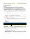
DE Mapping
The DE Mapping variable is used to determine how the Frame Relay DE field (Discard Eligibility) will be
mapped to the ATM CLPI (Cell Loss Priority Indication) and vise versa. The following options are available:
• Always_zero:
– Frame Relay: All Frame Relay packets will have the DE field in the header set to a constant value of 0.
– ATM: All ATM cells will have the CLPI field set to a constant value of 0.