


4 • Basic Application Configurations Model 3086 G.SHDSL Integrated Access Device User Guide
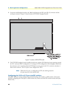
40 V.35 and X.21 Ports
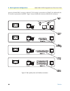
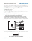
2. Locate the small daughter board on the 3086 board between the DSL port (RJ-45) connector and the
serial port connector (
Figure 7 shows location of DTE/DCE daughter board).
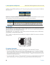
Figure 7. Location of DCE/DTE board
3. The DTE/DCE daughter board is installed at the factory with the DCE label and arrows pointing towards
the X.21 connector (DCE configuration). To change to DTE configuration, lift the daughter board from
the connector, turn it around so that the DTE label an arrows point to the X.21 connector, and place it
back on the connector. The X.21 port is now configured as a DTE.
Note
When the X.21 port is configured as a DTE, the clocking mode for
the port must be set for external clock.
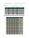
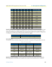
Configuring the V.35 or X.21 port via DIP switches
The 3086 TDM port can be configured via terminal interface, web interface, or DIP switches. This section
describes configuring the TDM port via DIP switches only. Please note that DIP switches modify serial port
features only.