


V.35 and X.21 Ports 39
Model 3086 G.SHDSL Integrated Access Device User Guide 4 • Basic Application Configurations
V.35 and X.21 Ports
The serial port in the 3086 is simple to install. The V.35 interface is wired as a DCE, the X.21 interface can be
configured as a DCE (factory default), or as a DTE via internal configuration jumper. The following sections
describe the 3086 X.21 and V.35 port connection to DTE and DCE devices.
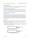
Connecting the 3086 serial port to a DTE
The serial port on the Model 3086 is configured as a DCE so it connects directly to a DTE using a standard
straight through cable. The cable should present either a male M/34 or DB-25 connector on one end, for V.35
interfaces, or a male DB-15 for X.21 interface connection. The other end should be terminated with the appro
-
priate connector ( check your DTE equipment manual for pinout, gender, and DTE/DCE port configuration).
Connecting the 3086 serial port to a DCE
V.35 interfaces.
The V.35 interface in the 3086 is wired as a DCE, no DTE configuration is possible. If the equipment that the
3086 is connecting to locally does not have the option for DTE configuration, a tail-circuit cable will be
required (this cable is available from most datacomm supply vendors). The tail-circuit cable will cross most
interface signals, so that the DCE interface of the 3086 and the DCE interface of the third party equipment
can function properly. Please be aware that some third party equipment will not be able to work properly in
DCE to DCE configurations even when using a tail circuit cable (please refer to your third party equipment
user manual for information on DCE-to DCE operation). The 3086 requires a cable with a male M/34 or
male DB-25 connector.
X.21 interfaces.
The Model 3086’s X.21 interface configuration can be modified, by the user, as DCE (factory default) or
DTE, via an internal jumper board. When the local third party equipment is configured as DCE, the Model
3086 X.21 serial port can be configured as DTE, and a regular straight through cable can then be used. Do the
following to configure the X.21 port as a DTE:
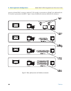
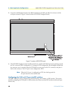
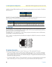
1. Open the 3086’s case by inserting a screwdriver into the slots and twist the screwdriver head slightly. The
top half of the case will separate from the lower half of the case (see
Figure 6). Take caution not to damage
any of the PC board mounted components.
Figure 6. Case being opened with screwdriver