


E1 Interface 49
Model 3086 G.SHDSL Integrated Access Device User Guide 4 • Basic Application Configurations
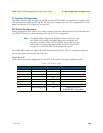
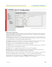
Line Build Out: Select from 100 ohm (0dB), 100 ohm (-7.5dB), 100 ohm (-15dB), and 100 ohm (-22.5dB).
For CSU/DSU application use 100 0dB option, consult your T1 service provider for more information.
FDL Mode: Options are ANSI-T1-403, ATT-54016, and Fdl-none. Consult your T1 service provider or third
party equipment for FDL mode required.
Idle code: Enabled, Disabled. When enabled, the 2603 inserts idle codes on unused timeslots. Set this option
to ‘Disabled’ unless instructed otherwise.
Power Down: Normal, Powered Down. When powered down, T1/E1 transceiver input and output lines will
be set to high impedance to protect the device—set unit to “Normal” for regular operation.
Once all options have been selected, click on the
Configure and Activate
at the bottom of the screen. Addition-
ally, save the configuration by going to the Configuration > Save Config menu.
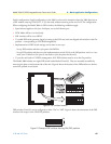
E1 Interface
The 3086 enables T1 or E1 device located at customer locations to access a carrier’s network over two wire,
long reach DSL links. This capability allows providers to offer T1/E1 services at customer locations that were
previously outside the reach of standard T1/E1 lines.
The 3086 offers a user configurable T1 or E1 interface. Selection of the interface is done via DIP switches,
HTTP/SNMP, or command line interface (CLI).
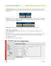
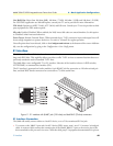
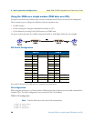
The E1 interface is presented on both a modular, 8-pin RJ-48C jack for connection to 120-ohm twisted pair
lines, and dual BNC female connectors for connection to 75-ohm coaxial lines.
Figure 11. E1 interface with RJ-48C jack (120–ohm) and dual BNC (75-ohm) connectors
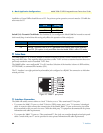
E1 Interface Connection
The 3086 will usually connect either to a local E1 device, or to a Telco terminated E1 line jack.
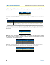
• To connect to the 3086 E1 port and a local E1 device (PBX, router, mux) use a E1 ‘crossover’ twisted pair
cable. A crossover cable connects the transmit pins of the Model 3086’s E1 port to the receive pins of the
device attached to this port and vice versa. Check the third party E1 equipment documentation for pinout