


33
Chapter 4 Basic Application Configurations
Chapter contents
Introduction..........................................................................................................................................................36
TDM Port.............................................................................................................................................................37
V.35 and X.21 Ports..............................................................................................................................................39
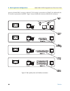
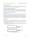
Connecting the 3086 serial port to a DTE ......................................................................................................39
Connecting the 3086 serial port to a DCE ......................................................................................................39
V.35 interfaces. .........................................................................................................................................39
X.21 interfaces. .........................................................................................................................................39
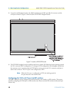
Configuring the V.35 or X.21 port via DIP switches ......................................................................................40
Switch Bank S2 .........................................................................................................................................42
Switches S2-1 through S2-7 ................................................................................................................ 42
Switch S2-8......................................................................................................................................... 43
Switch Bank S3 .........................................................................................................................................43
Switch S3-1: CO/CP selection ............................................................................................................ 43
Switch S3-3: Transmit Clock Mode.................................................................................................... 44
T1 Interface...........................................................................................................................................................44
T1 Interface Connection .................................................................................................................................44
T1 Interface Configuration .............................................................................................................................45
DIP Switch Configuration ..............................................................................................................................45
Switch Bank S2 .........................................................................................................................................45
Switches S2-1 through S2-7 ................................................................................................................ 46
Switch S2-8......................................................................................................................................... 46
Switch Bank S3 .........................................................................................................................................47
Switch S3-1: CO/CP selection ............................................................................................................ 47
Switch S3-3: Transmit Clock Mode.................................................................................................... 47
Switch S3-6: Annex............................................................................................................................. 48
Switch S3-7......................................................................................................................................... 48
Switch S3-8......................................................................................................................................... 48
Switch S3 applies to E1 applications, for T1 applications this switch is ignored. .......................................48
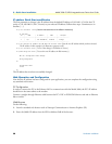
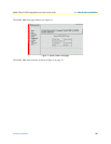
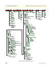
Web Interface Configuration ....................................................................................................................48
E1 Interface...........................................................................................................................................................49
E1 Interface Connection .................................................................................................................................49
DIP Switch Configuration ..............................................................................................................................50
Switch Bank S2 .........................................................................................................................................50
Switch S2-8......................................................................................................................................... 51
Switch Bank S3 .........................................................................................................................................51
Switch S3-1: CO/CP selection ............................................................................................................ 51
Switch S3-3: Transmit Clock Mode.................................................................................................... 52
Switch S3-6: Annex............................................................................................................................. 52
Switch S3-7......................................................................................................................................... 52