14
• If you attempt to modify any configuration parameters via the EOC (by
changing (EOC variables), the RocketLink-G will not execute your
changes.
3.3 CONFIGURING THE DIP SWITCHES
(V.35, X.21, and Ethernet
Models)
The Model 3088RC is equipped with three sets of DIP switches, which
you can use to configure the RocketLink-G for a broad range of applica-
tions. This section describes switch locations and discusses the configu-
ration options available.
Note By default, the RocketLink-G’s DIP switches are all set to “ON”
so the NTU can be configured via the console. If that is how you
will be configuring the NTU, skip ahead to the section on config-
uring the console.. Otherwise, read the following sections to
manually configure the DIP switch settings.
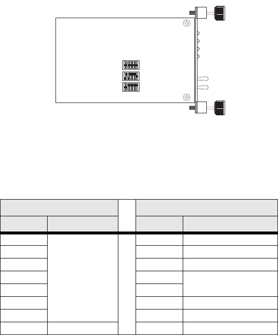
Figure 1. Location of DIP switches on Model 3088RC
The three sets of DIP switches on the Model 3088RC are referred to as
S1, S2 and S3. DIP switch orientation with respect to ON and OFF posi-
tions is consistent for all switches.
The DIP switches S1 and S2 can be configured as either ON or OFF.
S1 S2
Position Function Position Function
S1-1 Data Rate S2-1 Front Panel Switches
S1-2 S2-2 Line Probe
S1-3 S2-3 Annex
S1-4 S2-4 Clock Mode
S1-5 S2-5
S1-6 S2-6 DTE Loops
S1-7 S2-7 DTE Interface Type
S1-8 TX Clock S2-8 Reserved
S1
S2
S3


