


27
SGND & FRGND (JB4). In the connected position, this strap links Signal
Ground and frame ground through a 100 ohm resistor. In the open posi-
tion, signal ground is disconnected from frame ground.
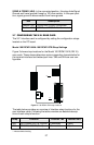
3.7 CONFIGURING THE X.21 REAR CARD
The X.21 interface card is configured by setting the configuration straps
located on the PC board.
Model 1001RCM11545& 1001RCM115TB Strap Settings
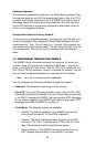
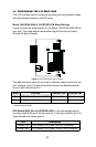
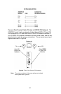
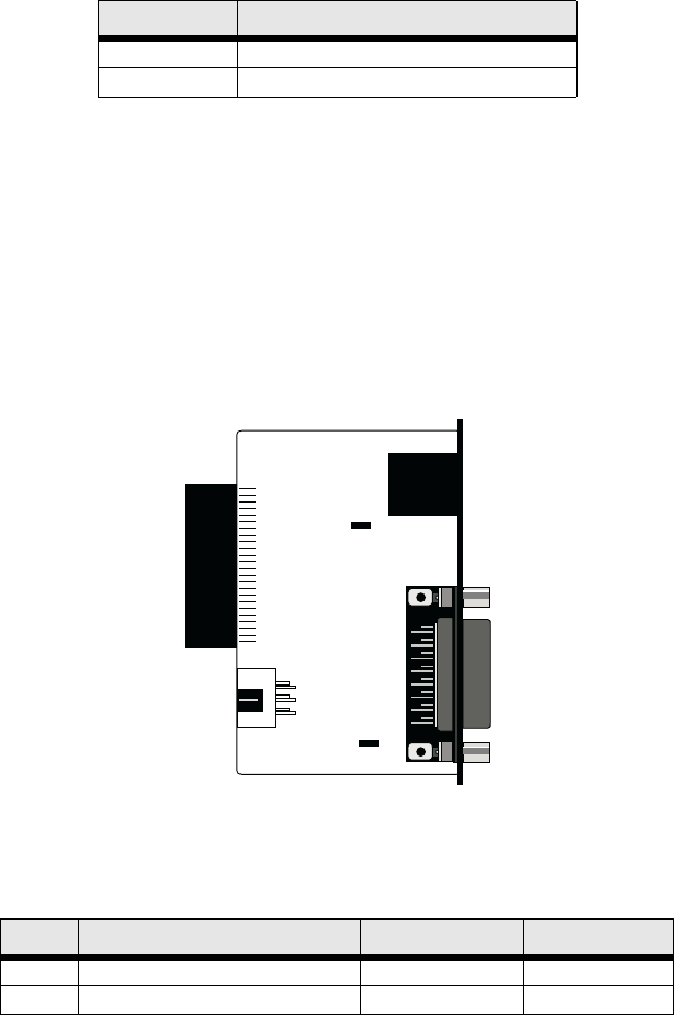
Figure 3 shows strap locations for the Model 1001RCM115XX (DB-15)
rear cards. These straps determine various grounding characteristics for
the terminal interface and twisted pair lines. JB3 and JB4 are user con-
figurable.
Figure 3. 1001RCM115XX strap locations
The table below provides an overview of interface strap functions for the
rear interface cards. Following the table overview are detailed descrip-
tions of each strap’s function.
* Indicates default setting
JB4 Description
Position 1&2 SGND and FRGND Connected
Position 2&3 SGND and FRGND Not Connected
Strap Function Position 1&2 Position 2&3
JB3 DTE Shield (Pin1) & FRGND Connected Open*
JB4 FRGND & SGND (Pin 8) Connected Open*
123
JB3
JB4
123