


43
4.0 INSTALLATION
This section describes the functions of the Model 1001R14 rack chassis,
tells how to install front and rear Model 3088RC Series cards into the
chassis, and how to connect to the twisted pair interface and the serial
interface.
4.1 THE MODEL 1001R14 RACK CHASSIS
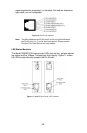
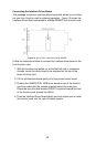
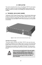
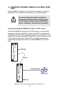
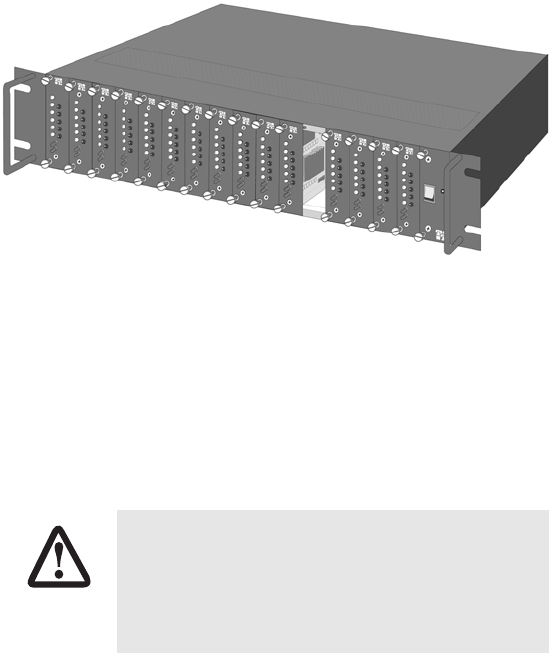
The Model 1001R14 Rack Chassis (Figure 17) has fourteen short range
modem card slots, plus its own power supply. Measuring only 3.5” high,
the Model 1001R14 is designed to occupy only 2U in a 19” rack. Sturdy
front handles allow the Model 1001R14 to be extracted and transported
conveniently.
Figure 17. Model 1001R14 Rack Chassis with power supply
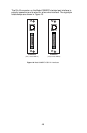
The Rack Power Supply
The power supply included in the Model 1001R14 rack uses the same
mid-plane architecture as the modem cards. The front card of the power
supply slides in from the front, and the rear card slides in from the rear.
They plug into one another in the middle of the rack. The front card is
then secured by thumb screws and the rear card by conventional metal
screws.
There are no user-serviceable parts in the power supply
section of the Model 3088RC Series. Voltage setting
changes and fuse replacement should only be per-
formed by qualified service personnel. Contact Patton
Electronics Technical support at (301) 975-1007 for
more information.
WARNING