


19
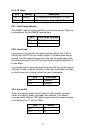
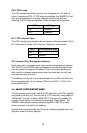
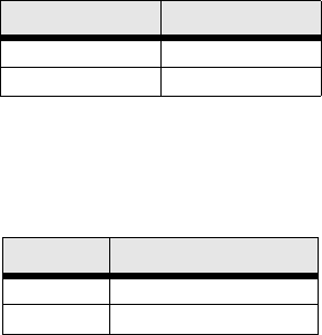
S2-6: DTE Loops
The V.35 interface provides two pins, one to request an LAL and the
other to request an RDL. If DTE loops are enabled, the 3088RC/A/I will
start a local loopback or a remote loopback when these pins are
asserted. If DTE loops are disabled, these requests will be ignored.
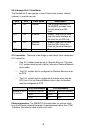
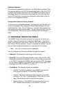
S2-7: DTE Interface Type
The DTE interface type needs to be set based on the rear module. Set to
E1 if using the /K model. Set to normal if using any other model.
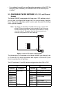
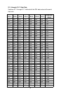
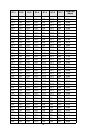
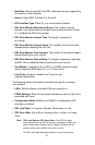
S3-1 through S3-8: Management Address
Each rack card in a chassis must have a unique management address.
The 1001CC and 1001MC use this address to activate and deactivate
the rack card's management interface. This is necessary because all
rack cards in a chassis communicate over the same bus, so only one
card can be active at a time.
This address can be set to any value between 0 and 255. Set S3 to the
binary representation of the number (ON=0 and OFF=1). S3-8 is the
most significant bit.
3.4 ABOUT SYSTEM RESET MODE
To enter system reset mode, switch all DIP switches to the OFF position
and power cycle the unit. You can use a VT100 emulator configured for
19200 bps/1 stop bit/ no parity/ XON-XOFF flow control to access the
console. Upon restart, you will see the message “Reset Mode”. The
3088RC automatically communicates through the 1001CC in reset
mode, and does not wait for its address.
System reset mode provides two functions: software upgrades and con-
figuration reset to factory defaults.
S2-6 Setting
ON Enabled
OFF Disabled
S2-7 DTE Interface Type
ON E1
OFF Normal