


Installing the IpChannel Bank 31
SmartNode 4400 Series Getting Started Guide 3 • Hardware installation
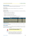
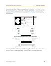
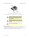
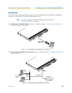
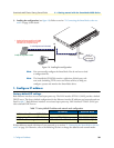
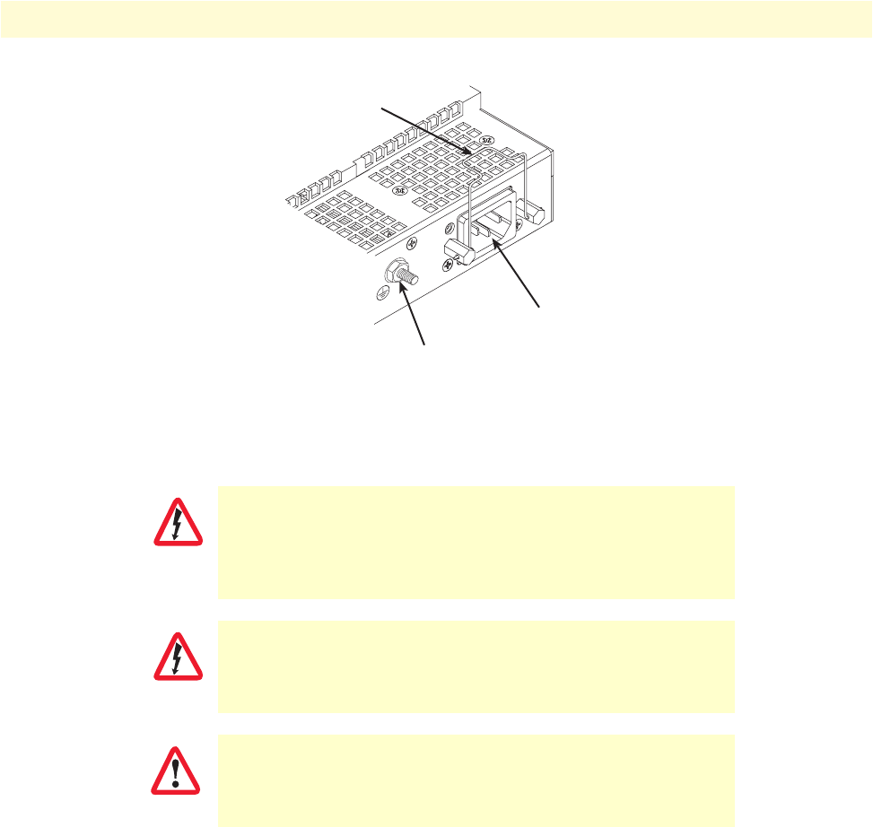
Figure 11. IEC-320 connector and grounding stud locations
2. Install the grounding wire between the grounding stud (see figure 11) and the grounding source.
Installing the power cables—AC units
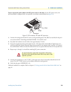
This section describes installing the power cables into the IEC-320 connectors on the IpChannel Bank. Do not
connect the remaining end of the power cables to the power outlet at this time. Do the following:
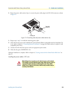
1. Install the power cable into an IEC-320 connector (see figure 11 on page 31). The AC mains socket outlet
shall be within 1 foot (3 meters) of the equipment and shall be easily accessible.
Mains Voltage: Do not open the case the when the power cord is attached.
Line voltages are present within the power supply when the power cords are
connected. The mains outlet that is utilized to power the device shall be
within 10 feet (3 meters) of the device, shall be easily accessible, and pro-
tected by a circuit breaker.
The Model SN4400 is not shipped with power cables. For AC powered units,
ensure that the power cable used meets all applicable standards for the coun-
try in which it is to be installed, and that it is connected to a wall outlet which
has earth ground.
The router power supply automatically adjusts to accept an input
voltage from 100 to 240 VAC(50/60 Hz).
Power cable
retainer clip
Grounding stud
IEC-320 connector
(2 places)
WARNING
WARNING
IMPORTANT