


Installing the IpChannel Bank 32
SmartNode 4400 Series Getting Started Guide 3 • Hardware installation
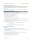
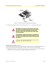
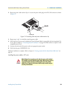
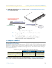
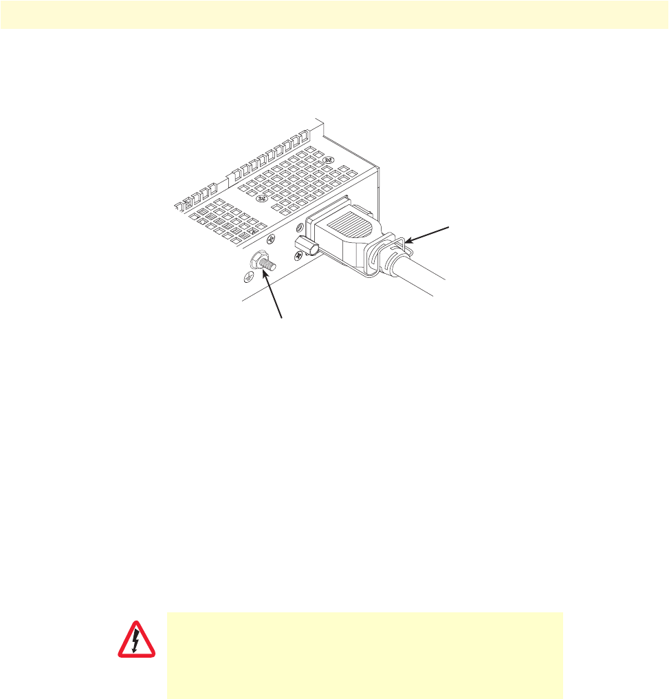
2. Rotate the power cable retainer clip so it secures the power cable plug in the IEC-320 connector as shown
in figure 12.
Figure 12. Grounding stud and power cable retainer clip
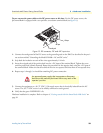
3. Repeat steps 1 and 2 to install the remaining power cable.
4. Verify that the AC power cord included with your IpChannel Bank is compatible with local standards. If it
is not, refer to chapter 5, “Contacting Patton for assistance” on page 44 to find out how to replace it with
compatible power cord.
5. Connect the male end of the power cord to an appropriate power outlet.
6. Verify that the green POWER LED is lit.
Hardware installation is complete. Refer to chapter 4, “Getting started with the SmartNode 4400 Series” on
page 34.
Installing the power cables—DC units
Mains Voltage: Do not open the case the when the power cord is attached.
Line voltages are present within the power supply when the power cords are
connected. The mains outlet that is utilized to power the devise shall be
within 10 feet (3 meters) of the device, shall be easily accessible, and pro-
tected by a circuit breaker.
Power cable
retainer clip
Grounding stud
WARNING