1. Configure IP address 36
SmartNode 4400 Series Getting Started Guide 4 • Getting started with the SmartNode 4400 Series
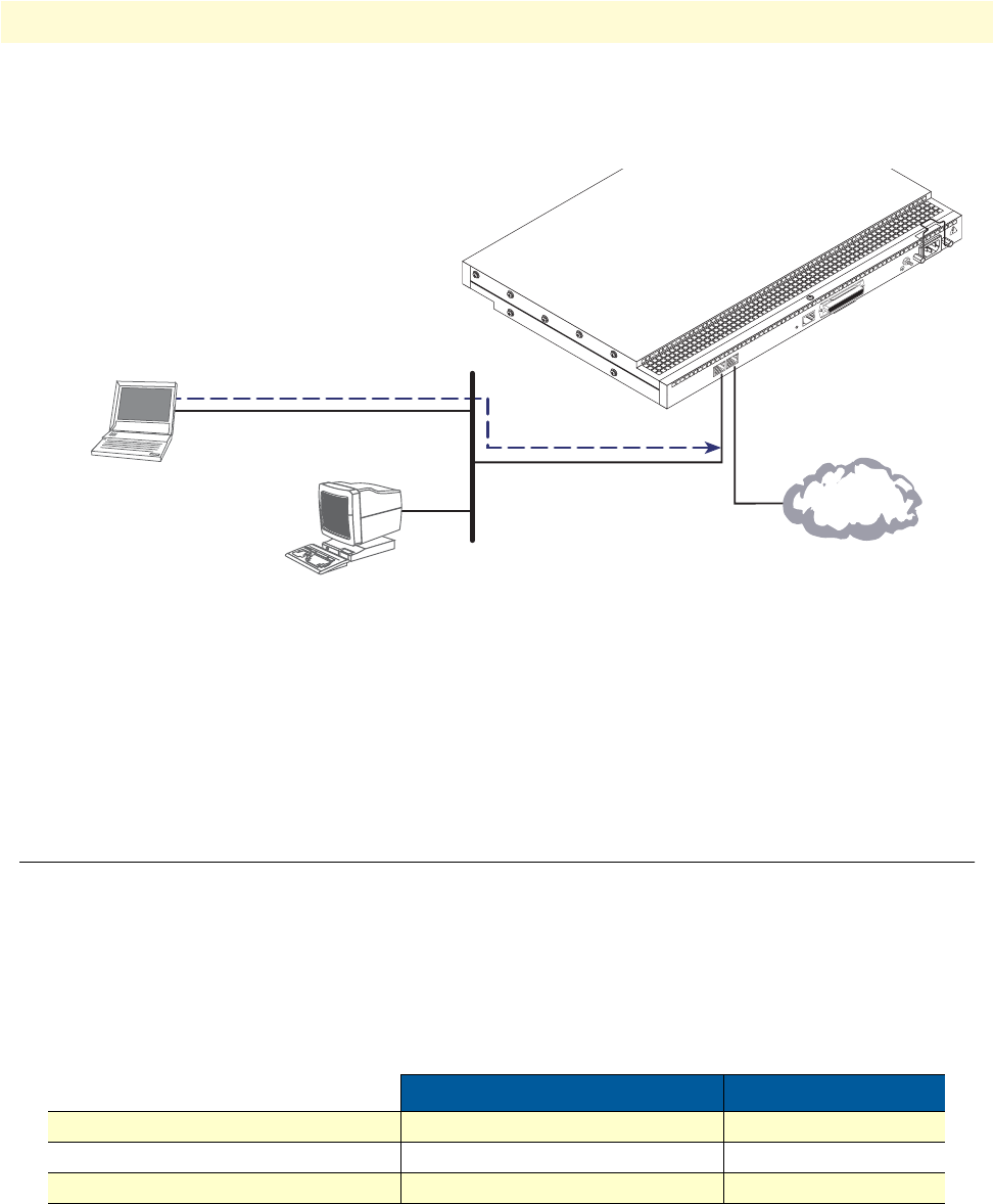
3. Loading the configuration (see figure 16). Refer to section “2. Connecting the SmartNode to the net-
work” on page 39 for details.
Figure 16. Loading the configuration
Note You can manually configure the SmartNode. You do not have to load
a configuration file.
Note The SmartNode CD-ROM contains a collection of third party soft-
ware tools (including TFTP servers and Telnet utilities) to help you
configure, operate and monitor the SmartNode device.
1. Configure IP address
Factory-default IP settings
Both Ethernet interfaces are activated upon power-up. The LAN interface ETH 0/1 (LAN) provides a default
DHCP server. The factory default configuration for the Ethernet interface IP addresses and network masks are
listed in table 7. Both Ethernet interfaces are activated upon power-up. LAN interface ETH 0/1 (LAN) pro-
vides a default DHCP server.
If these addresses match with those of your network, go to section “2. Connecting the SmartNode to the net-
work” on page 39. Otherwise, refer to the following sections to change the addresses and network masks.
Table 7. Factory default IP address and network mask configuration
IP Address Network Mask
WAN interface Ethernet 0 (ETH 0/0) DHCP DHCP
LAN interface Ethernet 1 (ETH 0/1) 192.168.1.1 255.255.255.0(/24)
DHCP IP address range 192.168.1.10 - 192.168.1.19 255.255.255.0(/24)
100-240V
(50-60 Hz)
1 AMP
UNIT EQUIPPED WITH DUAL SUPPLIES
DIS
CONNECT BOTH SUPPLIES
BEFORE SERVIC
I
NG
ETH 0/0
Console
Telco Ports
50
Reset
ETH 0/1
2. Modify the configuration as needed
3. Load configuration onto the SmartNode
1. Download configuration example from the CD-ROM
included with your SmartNode device or from the
Patton Web server at www.patton.com/voip
LAN (ETH 0/1)
LAN
Internet or
WAN (optional)
WAN
(ETH 0/0)


