IPLink Series High Speed Routers overview 22
Models 2603, 2621, and 2635 Getting Started Guide 1 • General Information
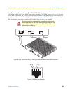
• Power input connector
• Ethernet connector
• MDI-X switch
• WAN port (V.35, X.21, T1/E1)
Power connector
AC universal power supply.
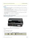
The IPLink Series router offers internal or external AC power supply options.
• The internal power supply connects to an AC source via an IEC-320 connector (100–240 VAC, 200 mA,
50/60 Hz)
• The external power supply connects to an external source providing +5 VDC via a barrel-type connector
48 VDC power supply.
• The DC power supply connects to a DC source via a terminal block
• Rated voltage and current: 36–60 VDC, 400 mA
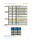
Ethernet port (outlined in green)
Shielded RJ-45 10Base-T/100Base-TX Ethernet port using pins 1,2,3, & 6. See MDI-X switch for hub or trans-
ceiver configuration.The following table defines conditions that occur when the MDI-X switch is in the out position.
MDI-X
The MDI-X push switch operates as follows:
• When in the default “out” position, the Ethernet circuitry takes on a straight-through MDI configuration
and functions as a transceiver. It will connect directly to a hub.
• When in the “in” position, the Ethernet circuitry is configured in cross-over MDI-X mode so that a
straight-through cable can connect The IPLink Series router’s Ethernet port directly to a PC’s NIC card.
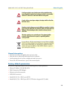
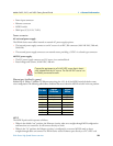
Connect the equipment to a 36–60 VDC source that is electri-
cally isolated from the AC source. The 36–60 VDC source is to
be reliably connected to earth.
Pin No.
Signal
Direction
Signal
Name
1 Output TX+
2 Output TX-
3 Input RX+
4 — —
5 — —
6 Input RX-
7 — —
8 — —
CAUTION


