


C2681M (2/08) 27
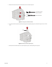
3. Point the antenna on the EW5001 toward the antenna on the other Endura wireless device.
4. Set the scale on the DVM for 0 VDC (zero VDC) to 6 VDC.
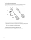
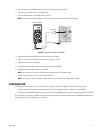
5. Uncap the RSSI connector on the EW5001 (refer to Figure 21).
NOTE: The cap is attached to the EW5001; you will reinstall it later to protect the unit from weather damage.
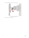
Figure 21. Connecting a DVM to the EW5001
6. Connect the DVM and a BNC adapter to the RSSI connector on the EW5001.
7. Adjust the antenna to achieve the best signal strength. The target is 3.3 VDC.
8. Tighten the antenna mounting hardware.
9. Disconnect the DVM and BNC adapter from the RSSI connector on the EW5001.
10. Reinstall the cap on the RSSI connector on the EW5001.
NOTE: Do not skip this step; you must reinstall the cap to protect the unit from weather damage.
11. Optional: Realign the antenna on the other Endura wireless device.
NOTE: Only realign the antenna if distance, weather, obstructions, or other factors are affecting signal strength.
CONFIGURATION
The EW5001 can be configured as an access point (default) or a bridge. To configure the EW5001, perform the following two steps:
1. Configure the network and wireless communication settings; refer to the supplied EW5001 Configuration manual (C2684M).
2. Configure the actual EW5001 Endura device settings; refer to the Endura WS5000 Advanced System Software Operation manual (C1624M).
Once configured, you can access the EW5001 the same way you access other Endura products. Refer to the Endura WS5000 Advanced System
Software Operation manual (C1624M) for more information.
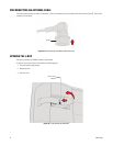
DIGITAL VOLTMETER
BNC ADAPTER
BNC CABLE
RSSI CONNECTOR
CAP