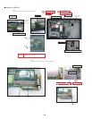
7-24
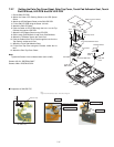
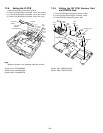
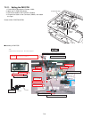
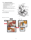
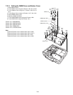
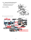
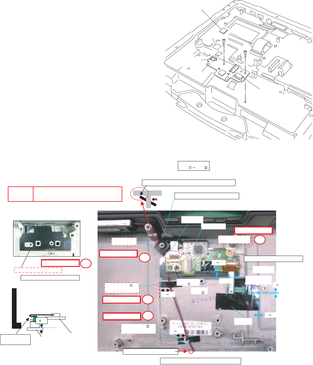
7.2.11. Setting the PAD PCB
1. Fix the PAD PCB using the 2 Screws. <N29>
2. Attach the TP PCB Screw Sheet.
3. Connect the Cable to the Connector. (CN802)
4. Connect the Cable to the Connector (CN801) and attach
the Tape.
Screws <N29>: DRQT26+E3FNL
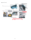
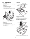
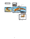
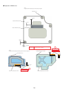
■ Assembly of PAD PCB
<N29>
<N29>
PadPCB
Connector
(CN802)
Connector
(CN801)
Tape
TPPCBScrewSheet
SafetyWorking
SafetyWorking
SafetyWorking
SafetyWorking
SafetyWorking
Attachthe
CableSheet
02
LEDPCB
AttachtheTouchPadINSSheet
02
711
711
02
02
FFCInsertion
FFCInsertion
AttachtheTouch
PadFFCFixTape
Tightenof
Screw
Tightenof
Screw
AttachtheTouchPad
PCBScrewSheet
CableHoldSheet
isinstalled
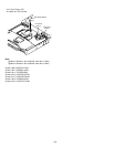
*Notes:
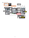
1.Applytheloadwhenattachingtheparts.20Nto30N(2to3Kgf)/cm2
Avoidrunningoverthebossandtherib.
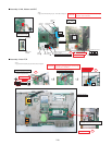
Processthesurplus
ofFFCtotheback.
Screw Screw
InsertthebossatanangletoputhereclosetotheCabinetside.
ProcesstheSPcablebetweenthebosses.
PCBPadisset
AttachtheTape
FittotheCabinetline.
AttachtheTape
FittotheCabinetline.
Processthewiretargetingtheboss.
DonotinserttheConnectoratanangle.
Orderoffixing
PCBPad
CNConnectionAfterconnecting,addthekaptontape.
S1:InsulationS2:PinchingCablesS3:SharpEdge
S4:PartNo.CheckS5:Others
CAUTION
S1
S1
S2
S2
S2


