7-32
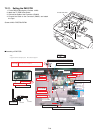
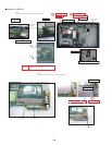
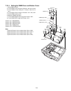
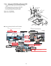
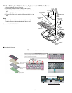
7.2.16. Setting the KB Cable Cover, Keyboard and LCD Cable Cover
1. Set the Keyboard onto the Computer.
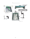
2. Connect the 2 Cables to the 2 Cables. (CN13,CN14)
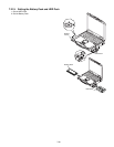
3. Fix the KB Cable Cover using the 7 Screws. <N29> No1 to
No7
4. Set the LCD Cable Plate.
5. Fix the LCD Cable Cover using the 3 Screws. <N29> No1 to
No3
Note:
Tighten the Screws in the numbered order (No1 to No7).
Tighten the Screws in the numbered order (No1 to No3).
Screws <N29>: DRQT26+E3FNL
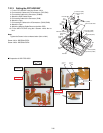
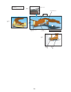
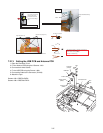
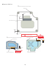
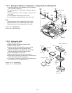
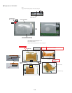
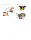
■ Arranging the Keyboard
<N29>
<N29>
<N29>
<N29>
<N29>
<N29>
<N29>
<N29>
<N29>
<N29>
toConnector
(CN14)
Connector
(CN13)
Connector
(CN14)
toConnector
(CN13)
KBCableCover
LCD
CableCover
LCD
CablePlate
Keyboard
No.6
No.4
No.1
No.5
No.3
No.7
No.2
No.1
No.2
No.3
AttachtheKeyboard
SpacerTape
AttachtheKeyboard
SpacerSheet
AttachtheKeyboard
BackPlate
KeyboardUSisinstalled
AttachtheKeyboardFookSpacerLower
Platehole
*Notes:
1.Applytheloadwhenattachingtheparts.20Nto30N(2to3Kgf)/cm2
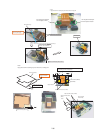
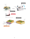
1.AttachtheKeyboardUSandKeyboardSpacer.(KBPreparation)
2.AttachtheKeyboardBackPlateandKeyboardSpacerSheet.(PlatePreparation)
(EnsureKeyboardSpacerSheetdoesnotrunoverthelevelofKeyboardBackPlate.)
3.AttachthepreparedKBtothepreparedplate.
(InserttheKBprotrusionsintotheplateholesanddeterminetheposition.)
:Fittotheedgeofplate(KBDbackplate).
Bothsidesshouldnotcomeovertheplate.


