7-27
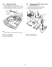
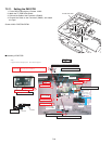
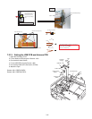
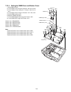
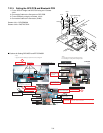
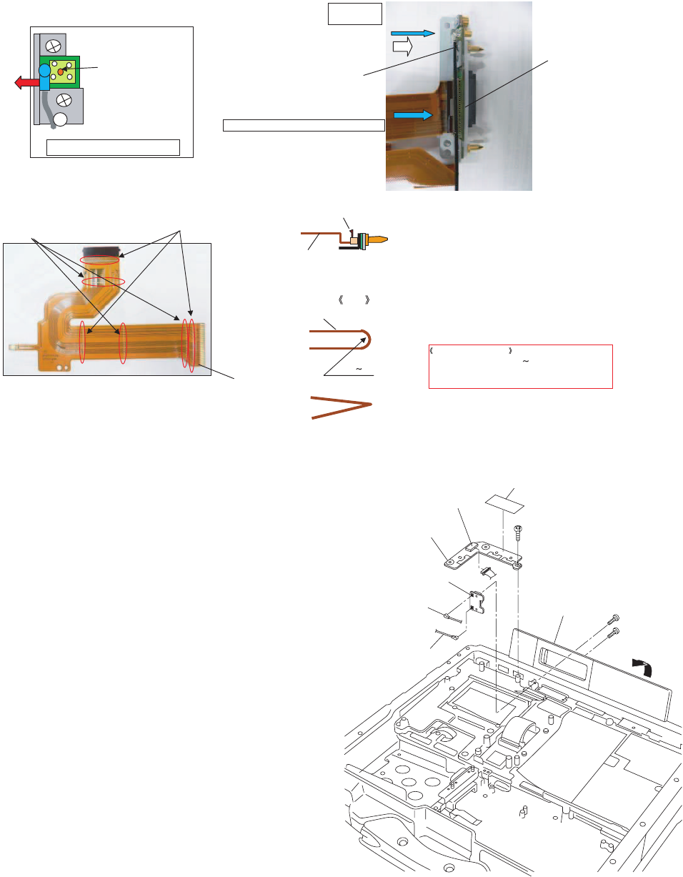
7.2.13. Setting the USB PCB and Antenna PCB
1. Open the Connector Cover.
2. Fix the Antenna PCB using the 2 Screws. <N3>
3. Connect the 2 white Cables.
4. Fix the USB PCB using the Screws. <N6>
5. Connect the Cable to the Connector. (CN100)
6. Attach the Tape.
Screws <N3>: DRQT2+G6FKL
Screws <N6>: DRQT26+E4FKL
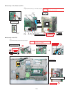
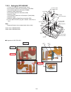
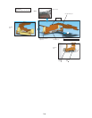
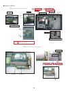
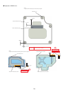
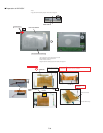
FPC
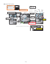
Theattentionoffolding:Breakagecountermeasure.
1,ThebendinginsideisR0.51
2,Don'tmistakeabendingdirection.
Don'tuseamistakenthing.
(R0.51)
NG
OK
FigureseenfromdirectionofarrowofA
Theterminaloftheantenna
cablemustnotcomein
contactwiththisterminal.
(Putitonthemetalfittings
side.)
Cable
RelayCircuitBoardAss'y
InsertFPCintoRelayCircuitBoardAss'yssocket
FPC
MountainFold(
StraightLine
)
ValleyFold(
DottedLine
)
InsertthePlug
intotheSocket
LockafterFPCinsertion
FIG
FPC
A
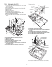
<N3>
<N3>
<N6>
USBPCB
Connector
(CN100)
AntennaPCB
ConnectorCover
AntennaCable
(White)
AntennaCable
(White)
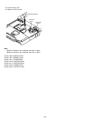
Tape


