7-31
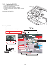
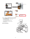
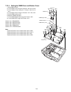
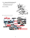
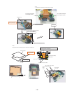
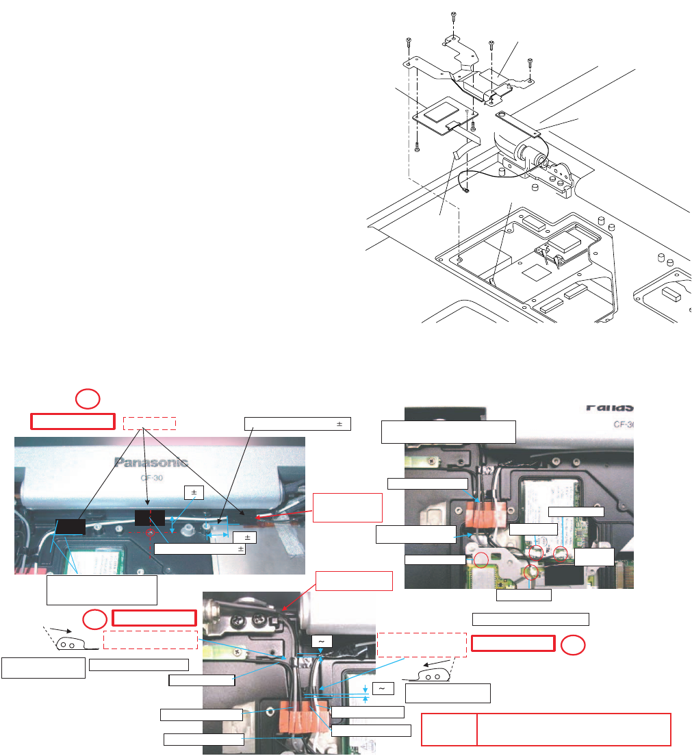
7.2.15. Setting the GPS PCB and Bluetooth PCB
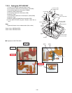
1. Fix the GPS BT Angle and GPS PCB using the 2 Screws.
<N11>
2. Connect the Cable to the Connector on GPS PCB.
3. Fix the GPS Ass’y using the 4 Screws. <N12>
4. Connect the Cable to the Connector. (CN25)
Screws <N11>: DFHE5025XA
Screws <N12>: DXQT2+F3FNL
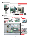
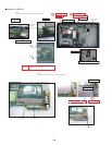
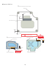
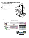
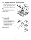
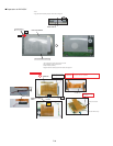
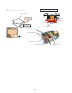
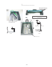
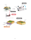
■ Cautions for Setting GPS ASSY and BT PCB ASSY
GPSPCB
Bluetooth
PCB
Connector(CN25)
<N11>
<N11>
GPSBTAngle
<N12>
<N12>
<N12>
<N12>
toConnector
(CN25)
SafetyWorking
SafetyWorking
SafetyWorking
81
102
MainAntenna
SubAntenna
BluetoothCable
WhipAntennaCable
WhipAntennaCable
MainAntennaCable
GPSAntennaCable
02
02
SubAntennaCable
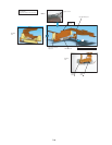
*Notes:
*Notes:
1.Applytheloadwhenattachingtheparts.20Nto30N(2to3Kgf)/cm2
Fittotheplatesqueezeline.1
AttachtheTape
PuttheCablealong
theCabinetsideand
tapeitfirmly.
Matchtothebosscenter.
CabinetLevelStandard
Tolerance0to1
Processthewireintothegroove.
PasstheCablebehind
theCabinetprotrusion.
AttachtheCableSheetinto
MainCableandWhipCable.
AttachtheCableSheetinto
SubCableandGPSCable.
Ensurethatthewrapping
directionisright.
Avoidcomingoverthegroove.
Ensurethatthewrapping
directionisright.
ConnectintothecoaxialConnector.
Processthewiretothe
backfromtheaperture.
Insertthe
cableplug.
ProcessthewireofwhipANTcablefrom
LCDtothebackfromtheaperture.
1.Donotgougewheninsertingandremovingtheplug.
2.Donotdamagethecoatingwhenhandlingthecable.
BluetoothCable
GPSAntenna
CAUTION
S1:InsulationS2:PinchingCablesS3:SharpEdge
S4:PartNo.CheckS5:Others
S2
S2
S2


