


17
16
SMARTSMART
PLUGPLUG
S-VIDEOS-VIDEO
VIDEOVIDEO
AUDIOAUDIO
VIDEOVIDEO
AUDIOAUDIO
OUTOUTININ
S-VIDEOS-VIDEOS-AUDIOS-AUDIO S-AUDIOS-AUDIO
RS 232RS 232
VIDEOVIDEO
AUDIOAUDIO
RF INRF IN
S-VIDEOS-VIDEO S-AUDIOS-AUDIO
CLONECLONE
PORTPORT
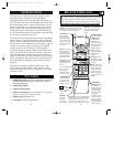
MENU
CH
VOL
POWER
+
–
▼ ▲
▼
▲
▼
▲
SLEEP
CC
2
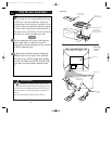
ANTENNA
IN
VIDEOAUDIO
IN
IN
OUTOUT
3
1
OUT
S-VIDEO
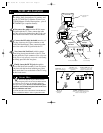
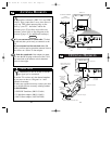
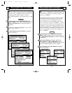
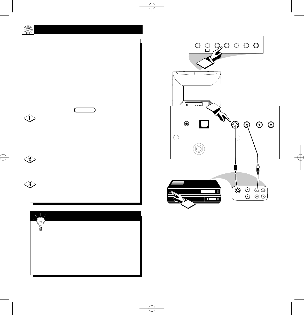
Optional S-VHS VCR
Rear Jacks of the
Net1Card Panel.
Back of TV
Front Control Panel of TV
S-VIDEO
Cable
(supplied with
optional S-
VHS VCR)
Audio RCA
Phono Plug
Cable
(not supplied)
Jack Panel of
Optional S-VHS VCR
S-VIDEO INPUTS
T
he S(uper)-Video connection on the rear of
the TV can give you better picture detail
and clarity, for the playback of S-VHS VCR
tapes, rather than the normal antenna picture
connections.
Note: The VCR (or accessory device) must
have a S-VIDEO OUT(put) jack in order for
you to complete the steps and connections
shown to the right.
Connect the S-VIDEO (S-VHS) OUT(put)
jack from the VCR (or other source) to the V-
VIDEO IN(put) jack on the TV.
Normally the S-VIDEO connecting cable will be
supplied with accessory devices supplied with a S-
VIDEO jack.
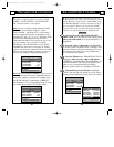
Press the CHANNEL ▼ button two channels
below the lowest broadcast channel to activate the
S-VIDEO inputs/outputs.
Turn the VCR ON. Insert a pre-recorded S-
VHS tape into the VCR. Press PLAY on the VCR
to view the tape on the TV.
BEGIN
Remember, after it is connected an easy
way to select the S-VIDEO mode is to scan
two channels below the lowest broadcast channel.
NOTE: If you have a stereo VCR, connect only
the red (or right) plug to the audio jack on the
back of the Net1Card.
SMART HELP
Net 1Card IB 2/15/00 12:17 PM Page 16