


Introduction to your PPS 2 - 3
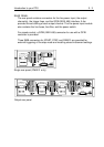
REAR PANEL
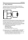
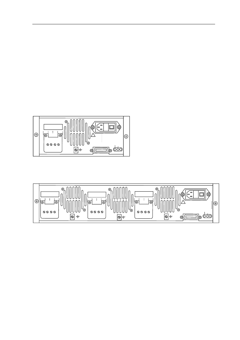
The rear panel contains connectors for the line power input, the output
channel(s), the trigger lines, and the GPIB (IEEE 488) interface. A fan
provides forced cooling of each output channel. The line power input module
also contains the line fuses, line filter, and the power switch.
For remote control, a GPIB (IEEE 488) connector for use with a GPIB
controller is provided.
Three SMB connectors for START, STEP, and READY are provided for
external triggering of the step mode and recalling stored instrument settings.
!
PHILIPS
IEEE488
STEP
START
READY
OUTPUT1
30V10A 60W
-S
-V
+V
+S
MAX
240V
!
FUSES
110V 2.5AT/250V
220V 1.25AT/250V
ST5825
PM2811/111
9448 02811011
No.DM000599
230V
50-60Hz
155VA
1
0
!
PHILIPS
IEEE488
STEP
START
READY
OUTPUT1
30V 10A60W
-S
-V
+V
+S
-S
-V
+V
+S
OUTPUT2
30V 10A60W
OUTPUT3
30V10A 60W
-S
-V
+V
+S
MAX
240V
MAX
240V
MAX
240V
!
!
!
FUSES
110V 6.3AM/250V
220V 3AT/250V
ST5824
0
1
PM2813/011
9448 02813011
No.DM521001
230V
50-60Hz
390VA
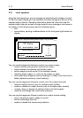
Output rear panel
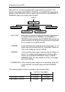
Single rear panel (PM2811 only)