


Installation Instructions 3 - 9
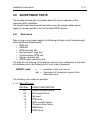
3.6 ACCEPTANCE TESTS
The acceptance tests
g
ive information about the correct operation of the
instrument after installation.
The interface test must be performed when usin
g
the pro
g
rammable power
supply for remote operation via the Controller/GPIB interface.
3.6.1 Brief check
After turnin
g
on your power supply, the followin
g
self tests on the hardware parts
will be performed automatically:
• ROM test
• RAM test
• GPIB controller test
• Microprocessor timer test
• Communication (D
2
B) test
• Display controller test
• ADDA output channel(s) test
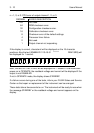
The tests will not show up on the display unless an error is detected. In the case
of a hardware error, the followin
g
text + error code is displayed:
ERROR n:ddd
n = Indication of the error source.
ddd = Summation of the decimal values of the
individual errors.
The followin
g
error codes are possible:
n = 0: Main CPU error
DECIMAL ERROR DESCRIPTION
128 Display controller failure.
64 Bank switch failure.
32 Not used.
16 D
2
B failure.
8 IEEE controller failure.
4 Processor timer failure.
2 RAM failure.
1 ROM failure.