


ActivMedia Robotics
! 4 Pulse-width-modulation ports (PWM1-4)
! 1 signal ground (Gnd)
! 1 Vcc (+5 VDC)
! 1 Vpp (+12 VDC)
Note that the general-purpose I/O and analog-to-digital ports are shared with the
General I/O connector (below) and joystick circuitry and may not be available for use
on all robots. For example, the analog lines P5_4-7, are used by the Joystick port, which
now comes standard with the Pioneer 2-AT and Performance PeopleBot. In addition,
four of the A/D ports and the PWM ports are shared with digital input and output lines,
respectively.
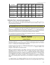
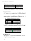
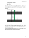
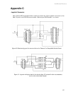
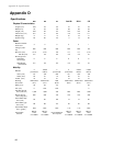
Table 20. User I/O Expansion Port
Pin
#
Label Use
Pin
#
Label Use
1
P2_12 OD0 or
PWM #1
2
P3_0 ID0
3
P2_13 OD1 or
PWM #2
4
P3_1 ID1
5
P2_14 OD2 or
PWM #3
6
P3_2 ID2
7
P2_15 OD3 or
PWM #4
8
P3_3 ID3
9
P5_4 ID4 or
A/D #1
10
P3_4 OD4
11
P5_5 ID5 or
A/D #2
12
P3_5 OD5
13
P5_6 ID6 or
A/D #3
14
P3_6 OD6
15
P5_7 ID7 or
A/D #4
16
P3_7 OD7
17
P5_9 A/D
#0/5
18
Vcc <100ma
19
Vpp <100ma
20
Gnd
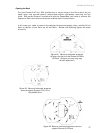
Performance PeopleBot I/O
The left and right Tabletop IR detectors on the Performance PeopleBot are connected to
the ID0 and ID1 digital input ports of the User I/O, respectively, which appear as bits 0
and 1 in the digin byte of the standard P2OS Server Information Packet. Normally high
(1), the digital input port goes low (0) when its respective Tabletop sensor detects an
object within its range of operation.
The left and right IR breakbeams are connected the User I/O digital input ports ID2 and
ID3, respectively. Normally high (1), the respective input port goes low (0) when an
object breaks the IR transmitter’s beam to its companion receiver.
61