


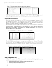

Appendix A: Microcontroller Ports and Connections
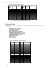
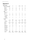
Table 21. Performance PeopleBot I/O
User
I/O
Pin #
Label Use
User
I/O
Pin #
Label
1
OD0
―
2
ID0 Lft Tabletop
3
OD1
―
4
ID1 Rgt Tabletop
5
OD2
―
6
ID2 Lft Breakbeam
7
OD3
―
8
ID3 Rgt Breakbeam
9
ID4 Joystick
10
OD4
―
11
ID5 Joystick
12
OD5
―
13
ID6 Joystick
14
OD6
―
15
ID7 E-Stop
16
OD7 -―
17
AD1
―
18
Vcc +5VDC
19
Vpp +12VDC
20
Gnd Gnd
― = Not used; available for other User applications
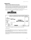
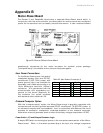
The General I/O Bus
The 34-pin IDC socket on the P2OS microcontroller provides a general-purpose I/O bus
containing:
! 8 read/write data lines (D0-7)
! 4 chip select lines (CS_2-5)
! 2 address lines (A0, A1)
! Read (RD#) and write (WR) lines
! 8 general-purpose digital I/O (P3_0-7)
! 1 analog-to-digital input (A/D) (P5_9)
! 4 PWM/digital output (P2_12-15)
! 2 signal ground (Gnd)
! 2 Vcc (+5 VDC)
! 1 Vpp (+12 VDC)
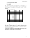
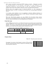
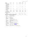
Table 22. General I/O Bus Connections
Pin # Label
Pin
#
Label
1
P3_0
2
D0
3
P3_1
4
D1
5
P3_2
6
D2
7
P3_3
8
D3
9
P3_4
10
D4
11
P3_5
12
D5
13
P3_6
14
D6
15
P3_7
16
D7
17
WR
18
CS2
19
Vpp
20
CS3
(Bumpers)
21
P2_12
22
CS4
23
P2_13
24
CS5
25
P2_14
26
A0
27
P2_15
28
A1
29
P5_9
30
Vcc
31
Gnd
32
RD#
33
Gnd
34
Vcc
62