


User’s Manual of GSD-800S / GSD-802S / GSD-802PS
4.5.3 VLAN setting example:
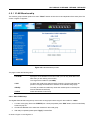
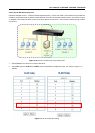
4.5.3.1 Two separate 802.1Q VLAN
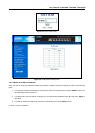
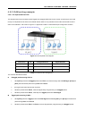
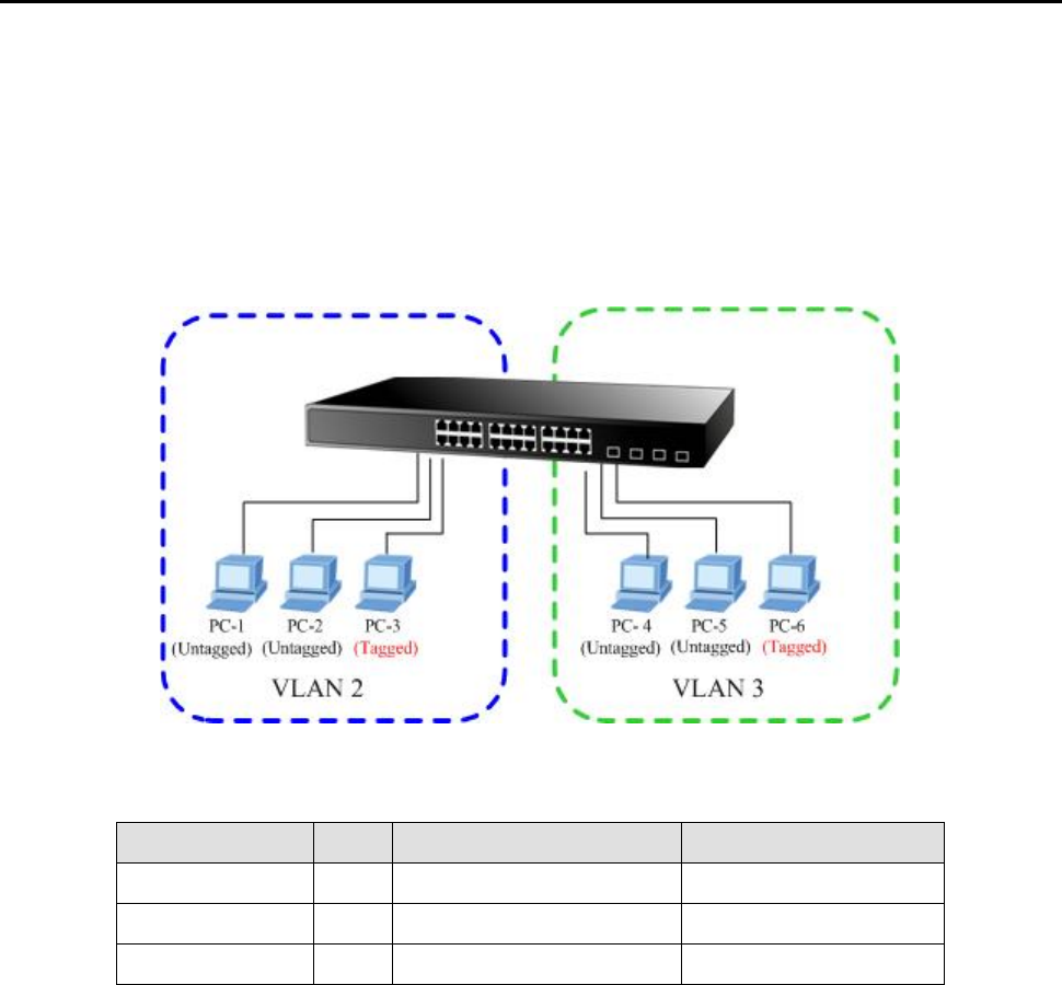
The diagram shows how the switch handle Tagged and Untagged traffic flow for two VLANs. VLAN Group 2 and VLAN
Group 3 are separated VLAN. Each VLAN isolate network traffic so only members of the VLAN receive traffic from the
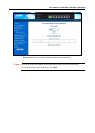
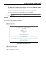
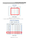
same VLAN members. The screen in Figure 4-11 appears and Table 4-1 describes the port configuration of switch.
Figure 4-11 two separate VLAN diagram
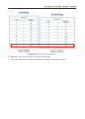
VLAN Group VID Untagged Members Tagged Members
VLAN Group 1 1 Port-7~Port-8 N/A
VLAN Group 2 2 Port-1,Port-2 Port-3
VLAN Group 3 3 Port-4,Port-5 Port-6
Table 4-1 VLAN and Port Configuration
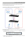
The scenario described as follow:
Untagged packet entering VALN 2
1. While [PC-1] transmit an untagged packet enters Port-1, the switch will tag it with a VLAN Tag=2. [PC-2] and
[PC-3] will received the packet through Port-2 and Port-3.
2. [PC-4],[PC-5] and [PC-6] received no packet.
3. While the packet leaves Port-2, it will be stripped away it tag becoming an untagged packet.
4. While the packet leaves Port-3, it will keep as a tagged packet with VLAN Tag=2.
Tagged packet entering VLAN 2
5. While [PC-3] transmit a tagged packet with VLAN Tag=2 enters Port-3, [PC-1] and [PC-2] will received the
packet through Port-1 and Port-2.
6. While the packet leaves Port-1 and Port-2, it will be stripped away it tag becoming an untagged packet.